
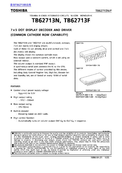
TOSHIBA TB62713N/TB62713F Manual


TOSHIBA TB62713N/TB62713F Manual - cover page
Brand
Toshiba
Category
Other Electronics
Document type
Datasheet
Language
English
Pages
25
File format
PDF
File size
993 KB
Published
07 June, 2012
Updated
29 June, 2012
MD5 checksum
BC233C6D6A19C64F3FB433FF2265F0A7

About this manual

The Toshiba TB62713N and TB62713F are multifunctional, compact Bi-CMOS integrated circuits designed as 7x5 dot matrix LED display drivers. These devices support common cathode row capability and can directly drive and control one 7x5 dot matrix LED display. The display shows the common cathode rows using a constant current for row output, which is set via an external resistor, while the column output utilizes standard PNP output.

What's inside

  • Features
  • Package Types
  • Pin Assignment
  • Equivalent Circuit Diagram
  • Pin Description
  • Timing Diagram
  • Description of Operation
  • Operating Mode Settings
  • Load Register Selection

Specifications

Row output rating17V/50mA
Maximum transmission frequency> fcLiK = 15MHz

Frequently asked questions

What is the maximum transmission frequency for serial data transmission?

The maximum transmission frequency is 15MHz.

How many steps can duty settings be made in?

Duty settings can be made in 16 steps from 0/16 to 15/16.

What is the typical weight of the SDIP24-P-300-1.78 package?

The typical weight is 1.62g.

Download PDF (993 KB)

More Toshiba Manuals


View all Toshiba manuals →