
This document is the introduction manual of Microchip Technology Inc. PIC17C7X6A series products. It introduces the features and characteristics of the series products, including the core features, peripheral features, special features and pin diagrams.
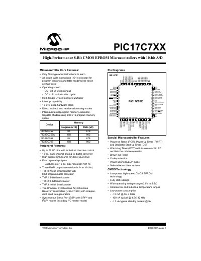
The document is a comprehensive data sheet for the Microchip PIC17C7XX family of 8-bit CMOS EPROM microcontrollers. It covers core features such as single-cycle instructions, hardware multipliers, and various timer resources including TMR0 through TMR3.
Key peripheral features detailed include up to 66 I/O pins with individual direction control, a 10-bit multi-channel analog-to-digital converter (A/D), and communication modules like USART/SCI and MSSP supporting SPI and I2C modes. The text also specifies device varieties, pin diagrams for different packages (LCC, TQFP, QFP), and special features such as Power-on Reset, Watchdog Timer, and Brown-out Reset. This manual is written in Chinese.
| Instruction Cycle Time (DC) | 121 ns |
|---|---|
| Operating Speed (Max Clock Input) | 33 MHz |
| Program Memory Size (PIC17C752) | 8K x 16 |
| Data Memory Size (PIC17C752) | 678 bytes |
| Program Memory Size (PIC17C756A) | 16K x 16 |
| Operating Voltage Range | 3.0V to 5.5V |
| A/D Converter Resolution | 10-bit |
The devices support an operating speed of up to 33 MHz clock input.
The typical standby current is less than 1 mA when operating at 5V.
These microcontrollers come in 68-pin LCC, 64-pin TQFP, and 80-pin QFP packages.