
AN122-1 is an application note on diodes, which introduces diode turn-on time, overvoltage and overvoltage protection.
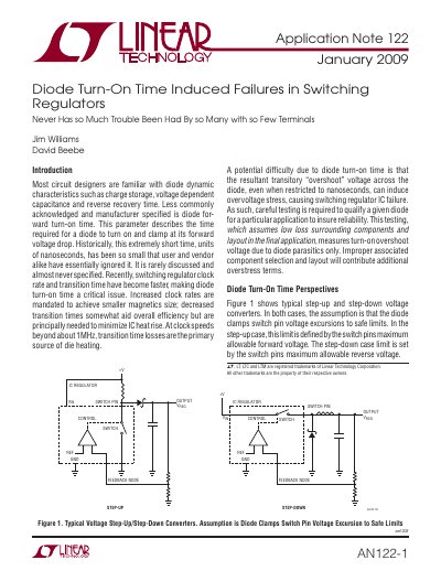
The document addresses the potential failure of switching regulator ICs caused by transient voltage overshoot resulting from finite diode turn-on times. It explains that while historically ignored due to short durations, this factor becomes critical at clock speeds beyond 1MHz and requires careful qualification testing to ensure reliability.
A detailed measurement scheme is proposed to characterize diode turn-on time under realistic operating conditions. The text specifies the necessary equipment, including a sub-nanosecond rise time pulse generator, a high-current amplifier, and a 1GHz oscilloscope, along with specific circuit configurations for accurate testing.
| Required Oscilloscope Bandwidth | 1GHz |
|---|---|
| Test Current Amplitude | 1A |
Finite turn-on time allows transient excursions above the nominal clamp voltage, potentially exceeding the IC's breakdown limit and causing failure.
The test is performed at 1A.
It overshoots for approximately 3.6ns.
It peaks 1V above the nominal 400mV V FWD.