
The LMF90 is a fourth-order elliptic notch (band-reject) filter based on switched-capacitor techniques. No external components are needed to define the response function. The depth of the notch is set using a two-level logic input, and the width is programmed using a three-level logic input. Two different notch depths and three different ratios of notch width to center frequency may be programmed by connecting these pins to Va, ground, or Vb. Another three-level logic pin sets the ratio of clock frequency to notch frequency. An internal crystal oscillator is provided. Used in conjunction with a low-cost color TV crystal and the internal clock frequency divider, a notch filter can be built with center frequency at 50 Hz, 60 Hz, 100 Hz, 120 Hz, 150 Hz, or 180 Hz for rejection of power line interference. Several LMF90s can be operated from a single crystal. An additional input is provided for an externally-generated clock signal.
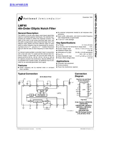
The LMF90 is a fourth‑order elliptic notch (band‑reject) filter based on switched‑capacitor techniques. No external components are required to set the response, and the notch depth is selected with a two‑level logic input while the width is set with a three‑level logic input. The device includes an internal crystal oscillator and can be configured for common power‑line frequencies such as 50 Hz, 60 Hz, 100 Hz, 120 Hz, 150 Hz, or 180 Hz.
Key specifications include a frequency range of 0.1 Hz to 30 kHz, selectable notch depths of 100:1, 50:1, or 33.3:1, and programmable notch bandwidths. The LMF90 is offered in several 14‑lead packages and is intended for applications such as automatic test equipment, communications, and power‑line interference rejection.
| Frequency range | 0.1 Hz to 30 kHz |
|---|---|
| Accuracy (max) | 1.5 % |
| Supply voltage range | 2 V to 7.5 V or 4 V to 15 V |
| Passband Ripple (typ) | 0.25 dB |
| Attenuation at fo (typ) | 39 dB or 48 dB (selectable) |
| Notch depth (selectable) | 100:1, 50:1, or 33.3:1 |
| Notch bandwidth (yp) | 0.127 fo, 0.26 fo, or 0.55 fo |
| Output offset voltage (max) | 120 mV |
The LMF90 offers selectable notch depths of 100:1, 50:1, or 33.3:1.
The device can operate from 2 V to 7.5 V or from 4 V to 15 V.
The typical passband ripple is 0.25 dB.