
This document covers the functions and descriptions of the MC9S12DP512, MC9S12DT512, MC9S12DJ512 and MC9S12A512 devices, as well as the instructions to follow in their design and manufacture.
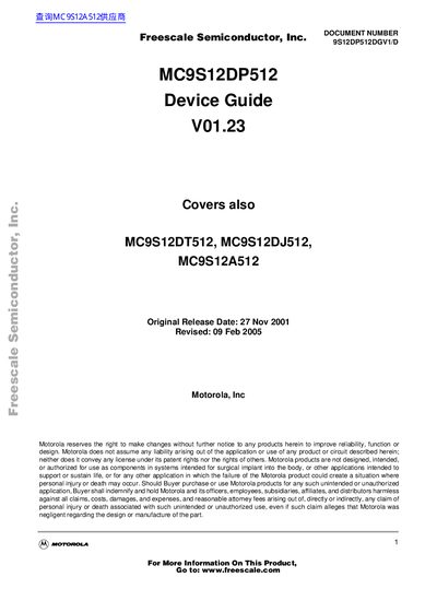
This device guide covers the MC9S12DP512 microcontroller, including its features, modes of operation, block diagram, and complete memory map. It provides detailed pinout information, signal properties, and power‑supply pin definitions.
The document also describes the system clock architecture, reset and interrupt handling, core block functions, and peripheral modules such as the ADC, SPI, SCI, PWM, and flash memory. Revision history and derivative differences are included for reference.
| Flash row size | 64 words per flash row |
|---|---|
| Sector erase size | 1024 bytes |
| Core supply voltage | 2.35 V (VDD and VDDPLL) |
| Input leakage current | 1 µA for all pins |
Each flash row contains 64 words.
The sector erase size is 1024 bytes.
Both VDD and VDDPLL are set to 2.35 V.
The input leakage current is 1 µA for all pins.