
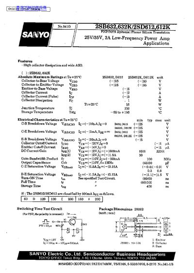
This datasheet describes the Sanyo 2SB632 (also listed as 632K) PNP/NPN epitaxial planar silicon transistor. It lists absolute maximum ratings, electrical characteristics, and typical application circuits for low‑frequency power amplification.
Key sections include specifications such as voltage ratings, current limits, gain, and power dissipation, as well as sample transformer‑coupled amplifier designs and test circuit details. The document also contains a disclaimer about intended use and liability.
| Collector-to-Emitter Voltage (Vceo) | 25 V (PNP) / 385 V (NPN) |
|---|---|
| Maximum Collector Current (Ic) | 2 A continuous, 3 A pulse |
| Collector Dissipation (P_D) | 1 W |
| Junction Temperature (Tj) | 150 °C |
| Voltage Gain (VG) without NFB | 75 dB |
| Output Power (P_o) at 5 % THD | 8.7 W |
The maximum continuous collector current is 2 A (with a 3 A pulse rating).
The transistor can handle 25 V in PNP mode and up to 385 V in NPN mode.
A voltage gain of 75 dB is specified without negative feedback.
The sample circuit delivers 8.7 W output power with a total harmonic distortion of 5 %.