
The TLPxxM/G/G-1 series are tripolar transient surge arrestors used for primary and secondary protection in sensitive telecom equipment. They feature tripolar crowbar protection, voltage range selected for telecom applications, repetitive peak pulse current, holding current, low capacitance, and low leakage current.
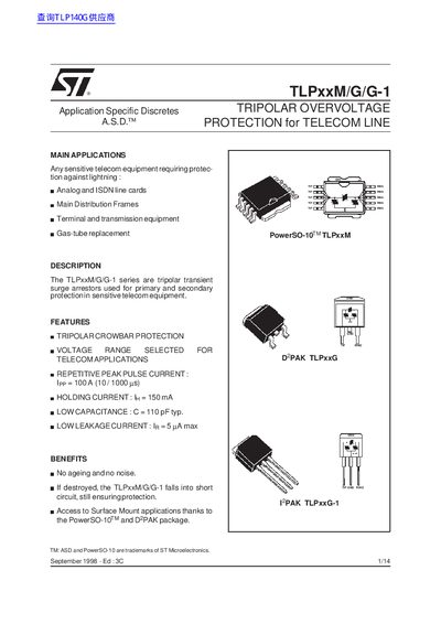
This handbook describes the TLPxxM/G/G-1 series of tripolar transient surge arrestors used for primary and secondary protection of sensitive telecom equipment. It covers the device description, key features such as a tripolar crowbar protection, low capacitance (110 pF typ.) and low leakage current (5 pA max), and benefits like no ageing and short‑circuit fallback.
The document includes detailed electrical characteristics, absolute maximum ratings, thermal resistance data, mechanical dimensions, package markings, and recommended mounting techniques on FR‑4 and IMS substrates. Test procedures for functional holding current (GO‑NO‑GO) and breakover voltage measurements are also provided.
| Peak pulse current (Ipp) | 100 A (10 µs/1000 µs) |
|---|---|
| Holding current (In) | 150 mA |
| Capacitance (C) | 110 pF typ. |
| Leakage current (Ir) | 5 pA max |
| Breakdown voltage (VBR) – CCITT K20 | 4000 V |
The series is rated for a peak pulse current of 100 A with a 10 µs/1000 µs waveform.
A GO‑NO‑GO test is used: the device is short‑circuited to set the holding current, then a surge of 10 A (10 µs/1000 µs) is applied and the device must turn off within 50 ms.