
The PTF 10125 is an internally matched, common source N-channel enhancement-mode lateral MOSFET intended for linear driver and final applications from 1.4 to 1.6 GHz, such as DAB/DRB. It is rated at 135 watts minimum power output. Nitride surface passivation and full gold metallization ensure excellent device lifetime and reliability.
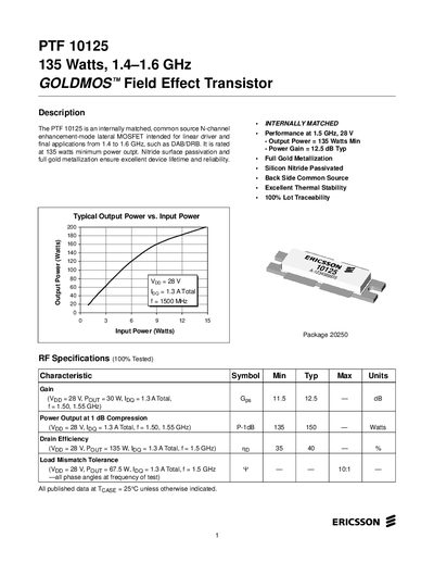
The PTF 10125 is an internally matched, common‑source N‑channel enhancement‑mode LDMOS transistor designed for linear driver applications in the 1.4‑1.6 GHz range, delivering up to 135 W output power. It features full gold metallization, silicon‑nitride passivation, and excellent thermal stability.
The document lists detailed electrical characteristics, maximum ratings, typical performance curves, impedance data, and a complete test‑circuit schematic. It also includes a parts layout and contact information for Ericsson Microelectronics.
| Typical Output Power (P‑1dB) | 135 W |
|---|---|
| Total Device Dissipation | 440 W |
| Power Gain (typ) | 12.5 dB |
| Thermal Resistance (Tcase = 70 °C) | 0.39 °C/W per side |
The typical output power at 1 dB compression is 135 W.
The device can operate up to a junction temperature of 200 °C.
Thermal resistance is 0.39 °C/W per side at Tcase = 70 °C.