
This document describes the MGFC45V5964A GaAs FET from 27-March'98 MITSUBISHI SEMICONDUCTOR. The product is a 50-ohm internally matched power FET designed for use in 5.9 - 6.4 GHz band amplifiers. It features high output power, high power gain, high power added efficiency, and low distortion.
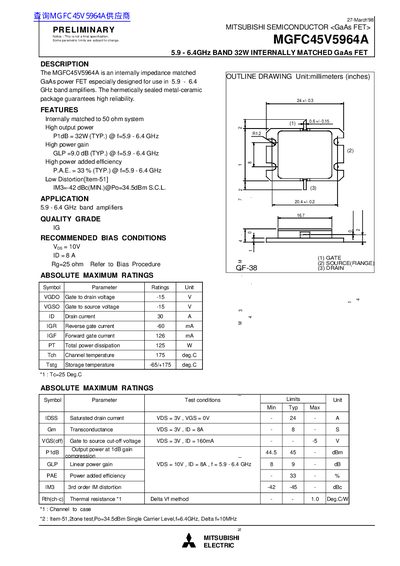
The MGFC45V5964A is a hermetically sealed, metal‑ceramic GaAs power FET designed for use in 5.9‑6.4 GHz band amplifiers. It is internally impedance‑matched to a 50 Ω system, providing high output power, gain and efficiency.
Key specifications include a typical P1dB of 32 W, linear gain of 9 dB, and power‑added efficiency of 33 % across the band. Absolute maximum ratings list a drain voltage of –15 V, drain current of 30 A, and total power dissipation of 125 W. Recommended bias conditions are Vgs = 10 V, Id = 8 A with a 25 Ω gate resistor.
| Frequency band | 5.9‑6.4 GHz |
|---|---|
| P1dB (typical output power) | 32 W @ 5.9‑6.4 GHz |
| Linear gain (GLP) | 9.0 dB @ 5.9‑6.4 GHz |
| Power added efficiency (PAE) | 33 % @ 5.9‑6.4 GHz |
| Third‑order intermodulation (IM3) | -42 dBc (min) @ Po=34.5 dBm |
| Gate‑to‑drain voltage (VGDO) | -15 V |
| Gate‑to‑source voltage (VGSO) | -15 V |
| Drain current (ID) | 30 A |
| Reverse gate current (IGR) | -60 mA |
| Forward gate current (IGF) | 126 mA |
| Total power dissipation (PT) | 125 W |
| Channel temperature (Tch) | 175 °C |
| Storage temperature (Tstg) | -65 °C to 175 °C |
| Transconductance (Gm) | 8 S |
| Gate‑to‑source cut‑off voltage (VGS(off)) | 5 V |
| Recommended bias – Vgs | 10 V |
| Recommended bias – Id | 8 A |
| Recommended bias – Gate resistor (Rg) | 25 Ω |
The typical P1dB is 32 W across the 5.9‑6.4 GHz band.
Use Vgs = 10 V, Id = 8 A and a 25 Ω gate resistor.
The drain current rating is 30 A and the gate‑to‑drain voltage rating is –15 V.
Typical PAE is 33 % at 5.9‑6.4 GHz.