
The MAX4820/MAX4821 8-channel relay drivers offer built-in kickback protection and drive +3.3V/+5V non- latching or dual-coil-latching relays. These devices are especially useful when driving +3V relays. Each inde- pendent open-drain output features a 2Ω on-resistance and is guaranteed to sink 70mA (min) of load current. Both devices consume less than 50µA (max) quiescent current and have 1µA output off-leakage current. The MAX4820 features an SPI™-/QSPI™-/MICROWIRE™- compatible serial interface. Input data is shifted into an 8- bit shift register and latched to the outputs when CS transitions from low to high. Each data bit in the shift reg- ister corresponds to a specific output, allowing indepen- dent control of all outputs. The MAX4821 features a 4-bit (A0, A1, A2, LVL) paral- lel-input interface. The first three bits (A0, A1, A2) deter- mine the output address, and the fourth bit (LVL) determines whether the selected output is switched on or off. Data is latched to the outputs when CS transi- tions from low to high. Both devices feature separate set and reset functions that allow the user to turn on or turn off all outputs simul- taneously with a single control line. Built-in hysteresis (Schmidt trigger) on all digital inputs allows this device to be used with slow rising and falling signals, such as those from optocouplers or RC power-up initialization circuits. The MAX4820/MAX4821 are available in 20-pin TSSOP and space-saving 20-pin thin QFN packag
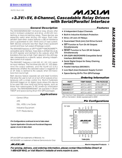
The MAX4820 and MAX4821 are 8‑channel relay driver ICs that provide built‑in kickback protection and can drive +3.3 V or +5 V non‑latching or dual‑coil latching relays. Each output is an open‑drain driver with a 2 Ω on‑resistance and a guaranteed 70 mA sink current.
Both devices support a serial interface compatible with SPI, QSPI and MICROWIRE (MAX4820) and a 4‑bit parallel interface (MAX4821). They feature separate SET and RESET pins for turning all outputs on or off, and a DOUT pin that enables daisy‑chaining of multiple devices. Packages are offered in 20‑pin TSSOP and 20‑pin thin QFN formats.
| Operating Voltage | 2.3 V – 5.5 V |
|---|---|
| Continuous Output Current (single channel) | 300 mA |
| Continuous Output Current (all channels) | 150 mA |
| Package Types | 20‑pin TSSOP, 20‑pin thin QFN |
The devices operate from 2.3 V up to 5.5 V.
Each device provides eight independent output channels.
Yes, the DOUT pin allows daisy‑chaining of multiple MAX4820 devices.
The MAX4820 supports a serial interface compatible with SPI, QSPI, and MICROWIRE.