
The MAX1708 sets a new standard of space savings for high-power, step-up DC-DC conversion. It delivers up to 10W at a fixed (3.3V or 5V) or adjustable (2.5V to 5.5V) output, using an on-chip power MOSFET from a +0.7V to +5V supply. Fixed-frequency PWM operation ensures that the switching noise spectrum is constrained to the 600kHz fundamental and its harmonics, allowing easy postfiltering for noise reduction. External clock synchronization capability allows for even tighter noise spectrum control. Quiescent power consumption is less than 1mW to extend operating time in battery-powered systems. Two control inputs (ONA, ONB) allow simple push-on, push-off control through a single momentary push-button switch, as well as conventional on/off logic control. The MAX1708 also features programmable soft-start and current limit for design flexibility and optimum performance with batteries. The maximum RMS switch current rating is 5A. For a device with a higher (10A) switch current rating, refer to the MAX1709 data sheet.
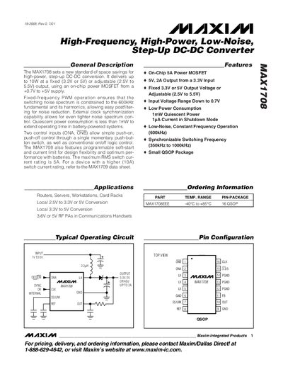
The MAX1708 is a high‑frequency, high‑power, low‑noise step‑up DC‑DC converter that delivers up to 10 W at fixed 3.3 V or 5 V, or adjustable 2.5 V to 5.5 V outputs. It operates from a supply as low as 0.7 V, features on‑chip 5 A power MOSFET, programmable soft‑start, and a maximum RMS switch current rating of 5 A. Applications include routers, servers, RF power amplifiers, and other battery‑powered systems.
The document includes absolute maximum ratings, detailed electrical characteristics, typical operating curves, pin descriptions, and layout recommendations. It also gives component selection guidance for diodes, input bypass capacitors, and output filter capacitors, as well as power‑dissipation calculations and PCB layout tips to ensure stable operation and efficient thermal management.
| Output Voltage | Fixed 3.3 V or 5 V, Adjustable 2.5 V‑5.5 V |
|---|---|
| Input Voltage Range | 0.7 V to 5.5 V |
| Maximum RMS Switch Current | 5 A |
| Quiescent Power Consumption | < 1 mW |
| Package | 16‑pin QSOP |
| Operating Temperature Range | -40 °C to +85 °C |
The device uses two control inputs, ONA and ONB, for push‑on/push‑off operation.
A high‑speed Schottky diode is recommended for the rectifier.
A 150 µF low‑ESR input capacitor is recommended to reduce peak currents and noise.
The MAX1708 can handle up to 5 A RMS switch current.