
The MAX1762/MAX1791 PWM step-down controllers provide high efficiency, excellent transient response, and high DC output accuracy needed for stepping down high-voltage batteries to generate low-voltage CPU core, I/O, and chipset RAM supplies in notebook computers and PDAs. Maxim's proprietary Quick-PWM™ pulse-width modulator is a free-running constant on-time type with input feed-forward. Its high operating frequency (300kHz) allows small external components to be utilized in PC board area-critical applications such as subnotebook computers and smart phones. PWM operation occurs at heavy loads, and automatic switchover to pulse-skip- ping operation occurs at lighter loads. The external high-side p-channel and low-side n-channel MOSFETs require no bootstrap components. The MAX1762/ MAX1791 are simple, easy to compensate, and do not have the noise sensitivity of conventional fixed-frequen- cy current-mode PWMs. These devices achieve high efficiency at a reduced cost by eliminating the current-sense resistor found in traditional current-mode PWMs. Efficiency is further enhanced by their ability to drive synchronous-rectifier MOSFETs. The MAX1762/MAX1791 come in a 10-pin µMAX package and offer two fixed voltages (Dual Mode™) for each device, 1.8V/2.5V/adj (MAX1762) and 3.3V/5.0V/adj (MAX1791).
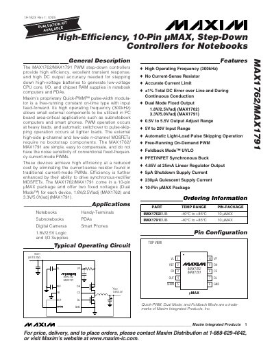
The MAX1762 and MAX1791 are 10‑pin µMAX step‑down controllers that convert high‑voltage battery sources (5 V‑20 V) to low‑voltage supplies for CPU cores, I/O, and RAM in notebooks, sub‑notebooks, PDAs, digital cameras and smart phones. They use Maxim’s Quick‑PWM™ constant‑on‑time architecture with a 300 kHz operating frequency, providing high efficiency and low component count.
Both devices offer dual‑mode fixed‑output options (1.8 V/2.5 V for MAX1762, 3.3 V/5.0 V for MAX1791) and an adjustable output range of 0.5 V‑5.5 V via an external resistor divider. The controllers drive external high‑side and low‑side MOSFETs without bootstrap components and support synchronous‑rectifier operation for further efficiency gains.
| Input Voltage Range | 5 V to 20 V |
|---|---|
| Fixed Output Voltages | 1.8 V/2.5 V (MAX1762) 3.3 V/5.0 V (MAX1791) |
| Adjustable Output Range | 0.5 V to 5.5 V |
| Operating Frequency | 300 kHz |
| Quiescent Supply Current (Shutdown) | 5 µA |
| Package | 10‑pin µMAX |
Both devices operate at a high frequency of 300 kHz.
They accept an input voltage from 5 V up to 20 V.
MAX1762 provides fixed 1.8 V or 2.5 V outputs, while MAX1791 provides fixed 3.3 V or 5.0 V outputs.
The shutdown supply current is 5 µA.