
The datasheet introduces the features and characteristics of the DS90LV049H product, including the high temperature operating range, data transmission rate, power supply, input and output pins, etc.
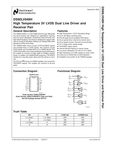
The DS90LV049H is a dual CMOS flow‑through differential line driver‑receiver pair designed for ultra‑low power dissipation, high noise immunity, and data rates exceeding 400 Mbps using LVDS technology. It translates LVTTL/LVCMOS signals to LVDS and vice‑versa, with internal fail‑safe biasing and a TRI‑STATE output control.
The document provides full electrical characteristics, absolute maximum ratings, switching performance, pin descriptions, mechanical dimensions, and application recommendations such as PCB layout, termination, and power‑decoupling guidelines. It also includes typical application circuits and compliance information.
| Operating Temperature Range | +125 °C |
|---|---|
| Maximum Data Rate | 400 Mbps |
| Supply Voltage | 3.3 V single supply |
| Power Dissipation (static) | 70 mW at 3.3 V |
| Package Type | 16‑lead TSSOP |
| Differential Output Voltage | 250‑450 mV |
The device supports data rates in excess of 400 Mbps.
It uses internal fail‑safe biasing that forces the output to a known high state when inputs are floating.
The TRI‑STATE function disables the outputs, providing a low idle power state when the device is not in use.