
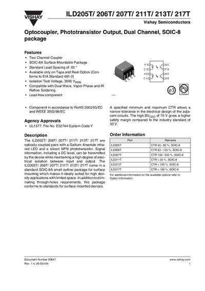
The ILD205T/206T/207T/211T/213T/217T family are dual‑channel optocouplers with a GaAs infrared LED and a silicon NPN phototransistor, offered in a surface‑mount SOIC‑8A package for high‑density applications. They feature isolation test voltages of 3000 V·µs, lead‑free RoHS‑compliant construction, and a range of current transfer ratios (CTR) tailored to different designs.
The datasheet lists absolute maximum ratings, electrical characteristics, switching performance, and mechanical dimensions. Key parameters include a collector‑emitter breakdown voltage of 70 V, power dissipation up to 125 mW per channel, and storage temperatures from –55 °C to +150 °C. Package dimensions and lead spacing are provided for PCB layout.
| Isolation test voltage | 3000 V·µs |
|---|---|
| Current Transfer Ratio (CTR) – ILD207T | 100 % – 200 % |
| Package type | SOIC‑8A surface‑mount |
| Power dissipation per channel | 125 mW |
The isolation test voltage is specified as 3000 V·µs.
The ILD207T offers a current transfer ratio of 100 % to 200 %.