
This document is a specification for the performance, test, quality, and reliability requirements of the MEG-Array™ 0.50” x .050” Grid High Density Connector System.
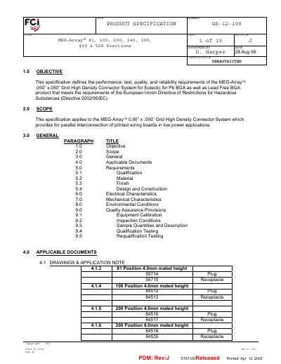
This specification outlines the objectives and scope for the MEG-Array™ 0.050" x 0.050" grid high‑density connector system, covering both eutectic Sn‑Pb and lead‑free BGA applications. It lists applicable standards, material requirements, and detailed design and construction rules.
Key sections include electrical characteristics such as contact resistance, insulation resistance, capacitance, and characteristic impedance, as well as mechanical characteristics like mating force and solder‑ball pull strength. Environmental testing procedures for temperature cycling, humidity, and corrosive atmospheres are also defined.
| Contact resistance (3.4 mm mated height) | 20 milliohms |
|---|---|
| Characteristic impedance (3.4 mm & 4.0 mm) | 50 ± 5 Ω |
| Solder ball alloy | 63 Sn/37 Pb or 95.5 Sn/4 Ag/0.5 Cu (lead‑free) |
The contact resistance shall not exceed 20 milliohms for a 4.0 mm mated height.
The specification calls for 63 Sn/37 Pb alloy or a lead‑free 95.5 Sn/4 Ag/0.5 Cu alloy.