
The MAX4533 is a quad, single-pole/double-throw (SPDT), fault-protected analog switch that is pin-compatible with the industry-standard MAX333 and MAX333A. It features fault-protected inputs and Rail-to-Rail® signal handling. The normally open (NO_ ) and normally closed (NC_ ) terminals are protected from overvoltage faults up to ±25V with power on and up to ±40V with power off. During a fault condition, NO_ and NC_ become high impedance with only nanoamperes of leakage current flowing to the source. In addition, the output (COM_) clamps to the appropriate polarity supply rail and provides up to ±10mA of load current. This ensures unambiguous rail-to-rail outputs when a fault occurs. The MAX4533 operates from dual ±4.5V to ±18V power supplies or a single +9V to +36V supply. All digital inputs have +0.8V and +2.4V logic thresholds, ensuring both TTL and CMOS logic compatibility when using ±15V supplies or a +12V supply. On-resistance is 175Ω max and is matched between switches to 10Ω max. The off- leakage current is only 0.5nA at TA = +25°C and 10nA at TA = +85°C. Applications include redundant/backup systems, portable instruments, test equipment, data-acquisition, communications systems, industrial and process control, and avionics systems.
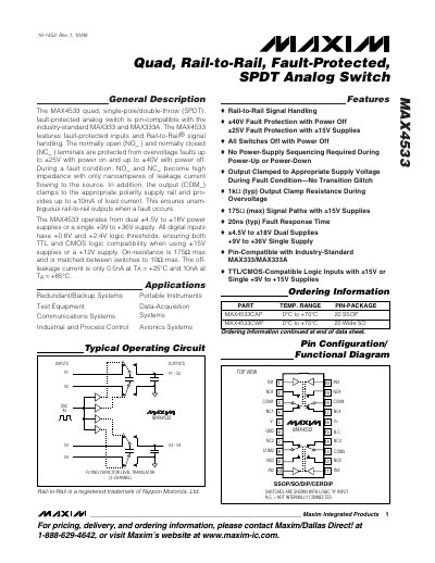
The MAX4533 is a quad, single‑pole/double‑throw (SPDT) analog switch that is pin‑compatible with the industry‑standard MAX333 and MAX333A. It features rail‑to‑rail signal handling, fault‑protected inputs, and can operate from dual ±4.5 V to ±18 V supplies or a single +9 V to +36 V supply. All digital inputs have logic thresholds of +0.8 V and +2.4 V, making the device compatible with TTL and CMOS logic.
Key specifications include an on‑resistance of up to 175 Ω, off‑leakage current as low as 0.5 nA at 25 °C, load current capability of ±10 mA, and fault protection of ±25 V with power on and ±40 V with power off. Typical fault response time is 20 ns, and the device operates over a wide temperature range from –40 °C to +125 °C.
| On‑Resistance (max) | 175 Ω |
|---|---|
| Off‑Leakage Current (typ, 25 °C) | 0.5 nA |
| Load Current | ±10 mA |
| Fault Protection (power on) | ±25 V |
| Fault Protection (power off) | ±40 V |
| Supply Voltage Range – Dual | ±4.5 V to ±18 V |
| Supply Voltage Range – Single | +9 V to +36 V |
| Logic Input Thresholds | +0.8 V (low), +2.4 V (high) |
| Typical Fault Response Time | 20 ns |
The device can tolerate up to ±40 V on the NO or NC pins when the power is off.
The on‑resistance is specified as a maximum of 175 Ω.
It operates from dual supplies of ±4.5 V to ±18 V or from a single supply of +9 V to +36 V.
The digital inputs have low‑level threshold of +0.8 V and high‑level threshold of +2.4 V.