
The MAX312F/MAX313F/MAX314F are quad single-pole/single-throw (SPST) fault-protected analog switches. They are pin compatible with the industry-standard nonprotected MAX312/MAX313/MAX314. These switches feature fault-protected inputs and Rail-to-Rail signal-handling capability. All analog signal terminals are protected from overvoltage faults up to ±36V with power on and up to ±40V with power off. During a fault condition, the COM_, NO_, or NC_ terminal becomes an open circuit and only microamperes of leakage current flow from the source. On-resistance is 10Ω (max) and is matched between switches to 0.5Ω (max) at +25°C. The MAX312F has four normally closed (NC) switches. The MAX313F has four normally open (NO) switches. The MAX314F has two NC and two NO switches. These CMOS switches operate with dual power supplies ranging from ±4.5V to ±20V or a single supply between +9V and +36V. All digital inputs have +0.8V and +2.4V logic thresholds, ensuring both TTL and CMOS logic compatibility when using ±15V or a single +12V supply. For supply voltages of ±5V, +5V, and +3V, refer to the MAX4711/MAX4712/MAX4713 data sheet. Applications include Communications Systems, Signal Routing, Test Equipment, Data Acquisition, Industrial and Process Control Systems, Avionics, Redundant/Backup Systems and ATE Hot Swap.
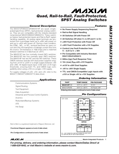
The MAX312F/MAX313F/MAX314F family are quad, single‑pole/single‑throw (SPST) analog switches with fault‑protected inputs and rail‑to‑rail signal handling. They are pin‑compatible with the industry‑standard non‑protected MAX312/MAX313/MAX314 devices and offer low on‑resistance (10 Ω max) with tight matching between channels (0.5 Ω max).\n\nThese CMOS switches operate from dual supplies of ±4.5 V to ±20 V or a single supply of +9 V to +36 V. They feature TTL‑ and CMOS‑compatible logic thresholds (+0.8 V low, +2.4 V high) and provide fault protection up to ±36 V when powered and ±40 V when power is off. Applications include communications systems, signal routing, test equipment, and industrial control.
| On‑Resistance (R_ON) max | 10 Ω |
|---|---|
| On‑Resistance match between channels | 0.5 Ω max |
| Dual‑supply voltage range | ±4.5 V to ±20 V |
| Single‑supply voltage range | +9 V to +36 V |
| Off‑leakage current | ±60 nA |