
The MAX2163 is a low-IF tuner IC designed for use in 1-segment ISDB-T applications. It directly converts UHF band signals to a low-IF using a broadband I/Q downconverter. The operating frequency range covers the UHF band from 470MHz to 806MHz. The MAX2163 includes LNAs, RF variable gain amplifiers, I and Q downconverting mixers, a baseband variable gain amplifier, and a low-IF filter. The MAX2163’s variable gain amplifiers provide in excess of 100dB of control range. The MAX2163 also includes fully monolithic VCOs as well as a complete frequency synthesizer including an on-chip crystal oscillator and output buffer. The device operates with a crystal from 32MHz to 36MHz. The MAX2163 features a 2-wire I2C-compatible serial-control interface. A low-power standby mode is available that shuts down the signal path, leaving the control interface and register circuits active. Additionally, an external pin can shut down the entire device. The MAX2163 is specified for operation in the extended -40°C to +85°C temperature range and is available in a 5mm x 5mm x 0.8mm, 28-pin thin QFN, lead-free plastic package with exposed paddle (EP).
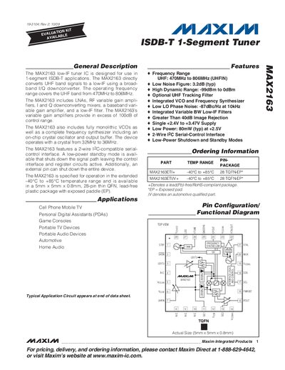
The MAX2163 is a low‑IF tuner IC designed for 1‑segment ISDB‑T applications. It converts UHF band signals (470 MHz‑806 MHz) to a low‑IF using a broadband I/Q downconverter and includes LNAs, RF variable‑gain amplifiers, I/Q mixers, a baseband variable‑gain amplifier, and a low‑IF filter. The device features a 2‑wire I²C‑compatible serial‑control interface, low‑power standby and shutdown modes, and operates from –40 °C to +85 °C.
Key specifications include a frequency range of 470 MHz‑806 MHz, a typical noise figure of 3.2 dB, over 100 dB of gain‑control range, supply voltage 2.4 V‑3.47 V, normal‑mode supply current of about 40 mA, and a 5 mm × 5 mm × 0.8 mm 28‑pin thin QFN package. The datasheet provides detailed pin descriptions, register maps, and guidance for RF gain control, VCO autoselection, and charge‑pump configuration.