
The MAX2160/EBG tuner ICs are designed for use in Japanese mobile digital TV (ISDB-T single-segment) applications. The devices directly convert UHF band signals to a low-IF using a broadband I/Q downconverter. The operating frequency range extends from 470MHz to 770MHz. The MAX2160/EBG support both I/Q low-IF interfaces as well as single low-IF interfaces, making the devices universal tuners for various digital demodulator IC implementations. The MAX2160/EBG include an LNA, RF variable-gain amplifiers, I and Q downconverting mixers, low-IF variable-gain amplifiers, and bandpass filters providing in excess of 42dB of image rejection. The parts are capable of operating with either high-side or low-side local oscillator (LO) injection. The MAX2160/EBG’s variable-gain amplifiers provide in excess of 100dB of gain-control range. The MAX2160/EBG also include fully monolithic VCOs and tank circuits, as well as a complete frequency synthesizer. The devices include a XTAL oscillator as well as a separate TCXO input buffer. The devices operate with XTAL/TCXO oscillators from 13MHz to 26MHz allowing the shared use of a VC-TCXO in cellular handset applications. Additionally, a divider is provided for the XTAL/TCXO oscillator allowing for simple and low-cost interfacing to various channel decoders. The MAX2160/EBG are specified for operation from -40°C to +85°C and available in a 40-pin (6mm x 6mm) thin QFN lead-free plastic package with exposed paddle (E
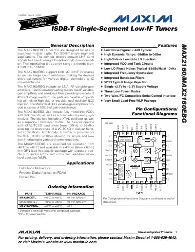
The MAX2160 and MAX2160EBG are low‑IF tuner ICs designed for Japanese mobile digital TV (ISDB‑T single‑segment). They convert UHF band signals to a low‑IF using a broadband I/Q down‑converter and support both I/Q and single low‑IF interfaces. The devices integrate LNA, variable‑gain amplifiers, mixers, filters and a complete frequency synthesizer in a compact QFN or wafer‑level package.
The datasheet provides detailed electrical characteristics, absolute maximum ratings, typical operating curves, pin descriptions and layout considerations. It also lists supply requirements, gain‑control ranges, noise figure, image rejection and other key performance parameters needed for system designers.
| Operating frequency range | 470 MHz – 770 MHz |
|---|---|
| Image rejection | ≥ 42 dB |
| Noise figure (typical) | < 4 dB |
| Supply voltage | 2.7 V – 3.3 V |
| Gain‑control range | > 100 dB |
The tuners operate from 470 MHz to 770 MHz.
The device works with a supply voltage between 2.7 V and 3.3 V.
Typical noise figure is less than 4 dB.
It provides at least 42 dB of image rejection.