
The MAX2120 low-cost, direct-conversion tuner IC is designed for satellite set-top and VSAT applications. The IC is intended for QPSK, Digital Video Broadcast (DVB-S), DSS, and free-to-air applications. The MAX2120 directly converts the satellite signals from the LNB to baseband using a broadband I/Q downconverter. The operating frequency range extends from 925MHz to 2175MHz. The device includes an LNA and an RF variable-gain amplifier, I and Q downconverting mixers, and baseband lowpass filters with programmable cutoff frequency control and digitally controlled baseband variable-gain amplifiers. Together, the RF and baseband variable-gain amplifiers provide more than 80dB of gain-control range. The IC is compatible with virtually all QPSK demodulators. The MAX2120 includes fully monolithic VCOs, as well as a complete frequency synthesizer. Additionally, an on- chip crystal oscillator is provided along with a buffered output for driving additional tuners and demodulators. Synthesizer programming and device configuration are accomplished with a 2-wire serial interface. The IC features a VCO autoselect (VAS) function that automatically selects the proper VCO. For multituner applications, the device can be configured to have one of two 2-wire interface addresses. A low-power standby mode is available whereupon the signal path is shut down while leaving the reference oscillator, digital interface, and buffer circuits active, providing a method to reduce power
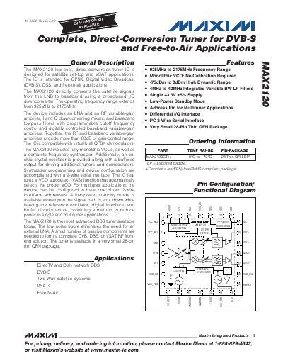
The MAX2120 is a low‑cost direct‑conversion tuner IC designed for satellite set‑top and VSAT applications. It converts LNB signals to baseband using a broadband I/Q down‑converter and includes an LNA, RF variable‑gain amplifier, mixers, programmable low‑pass filters and digitally controlled baseband gain stages.
Key features include a wide operating frequency range of 925 MHz to 2175 MHz, more than 80 dB of total gain‑control range, a monolithic VCO with auto‑select, a 2‑wire I²C serial interface for configuration, and a very small 28‑pin thin QFN package. The datasheet provides absolute maximum ratings, detailed electrical characteristics, pin descriptions, register maps and typical operating curves.
| Operating frequency range | 925 MHz to 2175 MHz |
|---|---|
| Total gain‑control range | >80 dB |
| Supply voltage (VCC) | 3.13 V to 3.47 V |
| Standby mode supply current | 3 mA |
The MAX2120 operates from 925 MHz up to 2175 MHz.
It provides more than 80 dB of gain‑control range.
Programming and configuration are done via a 2‑wire I²C serial interface.
The standby mode draws about 3 mA.