
The MAX2117 is a low-cost, direct-conversion tuner designed for receiving MMDS transmissions in the 470MHz to 1000MHz band. The MAX2117 is designed for use in consumer set-top boxes and is compatible with most DVB-S demodulators. The MAX2117 directly converts the QPSK broadcast signals from the antenna to baseband using a broadband I/Q downconverter. The tuner provides differential I and Q outputs to the demodulator IC. The device includes an LNA and an RF variable-gain amplifier, I and Q downconverting mixers, and baseband lowpass filters with programmable cutoff frequency control and digitally controlled baseband variable-gain amplifiers. Together, the RF and baseband variable-gain amplifiers provide more than 80dB of gain-control range. The IC is compatible with virtually all QPSK demodulators. The MAX2117 includes fully monolithic VCOs, as well as a complete frequency synthesizer. Additionally, an on-chip crystal oscillator is provided along with a buffered output for driving additional tuners and demodulators. Synthesizer programming and device configuration are accomplished with a 2-wire serial interface. The IC features a VCO autoselect (VAS) function that automatically selects the proper VCO. For multituner applications, the device can be configured to have one of two 2-wire interface addresses. A low-power standby mode is available whereupon the signal path is shut down while leaving the reference oscillator, digital interface, and buffer
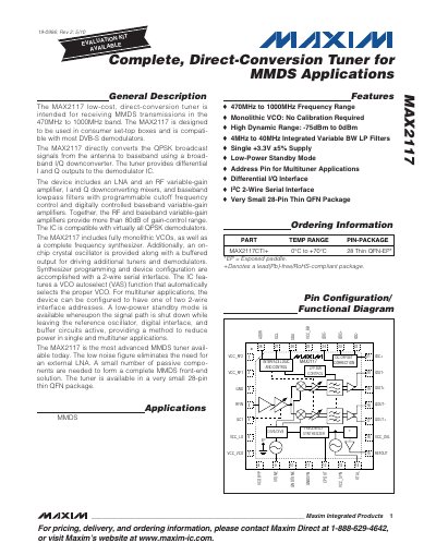
The MAX2117 is a low‑cost, direct‑conversion tuner designed for MMDS (470 MHz – 1000 MHz) reception in consumer set‑top boxes. It integrates an LNA, RF variable‑gain amplifier, I/Q down‑converter, programmable baseband filters, and a fully monolithic VCO and frequency synthesizer, all in a 28‑pin thin QFN package.
The device is programmed via a 2‑wire I²C serial interface and supports VCO autoselect, standby power‑saving mode, and dual‑address configuration for multituner applications. Detailed electrical characteristics, pin functions, and register maps are provided for designers. This manual is written in Chinese.
| Frequency Range | 470 MHz – 1000 MHz |
|---|---|
| RF Gain‑Control Range | more than 80 dB |
| Supply Voltage (VCC) | 3.13 V – 3.47 V |
| Standby Mode Supply Current | 3 mA |
| Package | 28‑pin thin QFN |
The RF gain‑control range exceeds 80 dB.
The MAX2117 includes 24 VCOs.
It operates from 3.13 V to 3.47 V.
It is offered in a 28‑pin thin QFN package.