
The HIP6601A, HIP6603A, and HIP6604 are high-frequency, dual MOSFET drivers specifically designed to drive two power N-Channel MOSFETs in a synchronous rectified buck converter topology. These drivers combined with a HIP63xx or an ISL65xx Multi-Phase Buck PWM controller form a complete core-voltage regulator solution for advanced microprocessors. The HIP6601A drives the lower gate in a synchronous rectifier to 12V, while the upper gate can be independently driven over a range from 5V to 12V. The HIP6603A drives both upper and lower gates over a range of 5V to 12V. This drive-voltage flexibility provides the advantage of optimizing applications involving trade-offs between switching losses and conduction losses. The HIP6604 can be configured as either a HIP6601A or a HIP6603A. The output drivers in the HIP6601A, HIP6603A, and HIP6604 have the capacity to efficiently switch power MOSFETs at frequencies up to 2MHz. Each driver is capable of driving a 3000pF load with a 30ns propagation delay and 50ns transition time. These products implement bootstrap
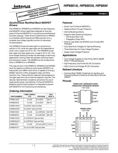
The HIP6601A, HIP6603A and HIP6604 drivers are designed to control two N‑Channel MOSFETs in synchronous‑rectified buck converter topologies. They support gate‑drive voltages from 5 V to 12 V, provide adaptive shoot‑through protection, and can switch MOSFETs at frequencies up to 2 MHz.
These devices are offered in 8‑lead SOIC, 8‑lead EPSOIC and 16‑lead QFN packages. Electrical specifications include a 3000 pF load capability with 30 ns propagation delay, 50 ns transition time, and a maximum power dissipation of about 800 mW for the SO‑8 package. The datasheet also details pin functions, timing diagrams, and recommended bootstrap capacitor requirements.
| Maximum Switching Frequency | 2 MHz |
|---|---|
| Load Capacitance Capability | 3000 pF |
| Ambient Temperature Range | 0 °C to 85 °C |
| Maximum Junction Temperature (Plastic Package) | 150 °C |
| Maximum Power Dissipation (SO‑8) | ≈ 800 mW |
The drivers can switch power MOSFETs at frequencies up to 2 MHz.
Adaptive shoot‑through protection is integrated to prevent simultaneous conduction of the upper and lower MOSFETs.
They are offered in Small 8‑lead SOIC, 8‑lead EPSOIC, and 16‑lead QFN packages.
The bootstrap capacitor must have a voltage rating above VCC + 5 V.