
Designed for pulse width modulated (PWM) current control of DC motors, the A3959 is capable of output currents to ±3 A and operating voltages to 50 V. Internal fixed off-time PWM current- control timing circuitry can be adjusted via control inputs to operate in slow, fast, and mixed current-decay modes. PHASE and ENABLE input terminals are provided for use in controlling the speed and direction of a DC motor with externally applied PWM-control signals. Internal synchronous rectification control circuitry is provided to reduce power dissipation during PWM operation. Internal circuit protection includes thermal shutdown with hysteresis, undervoltage monitoring of supply and charge pump, and crossover-current protection. Special power-up sequencing is not required. The A3959 provides a choice of three power packages, a 24-pin DIP with batwing tabs (package suffix ‘B’), a 24-lead SOIC with four internally-fused pins (package suffix ‘LB’), and a thin (<1.2 mm) 28-pin TSSOP with an exposed thermal pad (suffix ‘LP’). In all cases, the power pins and tabs are at ground potential and need no electrical isolation. Each package is lead (Pb) free, with 100% matte tin leadframes.
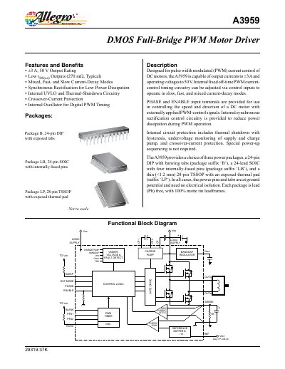
The Allegro A3959 is a DMOS full‑bridge PWM motor driver designed for pulse‑width‑modulated current control of DC motors. It delivers up to ±3 A output current at a maximum 50 V supply and includes internal protection features such as thermal shutdown, undervoltage lockout and crossover‑current protection.
The device is offered in three lead‑frame packages (24‑pin DIP, 24‑lead SOIC and 28‑pin TSSOP) with lead‑free, 100 % matte‑tin construction. Detailed electrical, thermal and layout guidelines are provided to aid designers in implementing the driver in motor‑control applications.
| Output Current Rating | ±3 A |
|---|---|
| Maximum Supply Voltage (VBB) | 50 V |
| Low rDS(on) Typical | 270 mΩ |
| Current‑Decay Modes | Mixed, Fast, Slow |
| UVLO Enable Threshold (VDD) | 3.90 V – 4.45 V |
The device can source or sink up to ±3 A of continuous current.
It operates with a supply voltage (VBB) up to 50 V.
It includes thermal shutdown with hysteresis, undervoltage lockout, and crossover‑current protection.