
Key facts
- Manuals
- 177
- Models
- 26
- Languages
- EN
- Last added
- 2012-08-09
Allegro models by category
Featured Allegro manuals
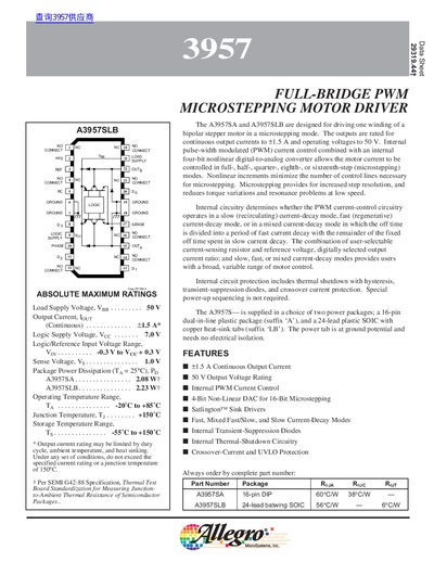
Allegro A3957SA/A3957SLB Full-Bridge PWM Microstepping Motor Driver Datasheet
The A3957SA and A3957SLB are full‑bridge PWM motor driver ICs designed to drive one winding of a bipolar stepper motor in microstepping mode. They provide continuous output currents up to ±1.5 A, support supply voltages up to 50 V, and include internal PWM current control, a 4‑bit non‑linear DAC, and selectable current‑decay modes (slow, fast, mixed).
Electrical specifications include a logic supply range of 4.5‑5.5 V, PWM turn‑off times of 18.2‑22.3 µs, and a thermal‑shutdown temperature of 165 °C. The devices are offered in a 16‑pin DIP (A3957SA) or a 24‑lead SOIC (A3957SLB) package, with detailed pin assignments for PWM control, sense, and output connections.
Covers: Features · Absolute Maximum Ratings · Electrical Characteristics · Functional Description · Current‑Decay Modes · Terminal Functions
Latest Allegro manuals
Allegro SLA7024M SLA7026M SMA7029M handbook
SLA7024M, SLA7026M, and SMA7029M are designed for high-efficiency and high-performance operation of 2-phase, unipolar stepper motors. The products are suitable for controlling and directly driving a broad range of 2-phase, unipolar stepper motors.
Allegro 2526/2536 handbook
The A2526EL/M and A2536EL/M are integrated high-side dual power switches, optimized for self-powered and bus-powered Universal Serial Bus (USB) applications. Few external components are necessary to satisfy USB requirements. Each switch channel supplies up to 500 mA as required by USB peripheral devices. In addition, the switch’s low on-resistance permits achieving the USB voltage-drop requirements. Fault current is limited to typically 750 mA, satisfying the UL 25 VA safety requirements, and a flag output is available to indicate a fault condition to the local USB controller. Momentary voltage drops that may occur on the upstream port when the switch is enabled in bus-powered applications is eliminated by a “soft start” feature. Additional features include thermal shutdown to prevent catastrophic switch failure from high-current loads, undervoltage lockout to ensure that the device remains OFF unless there is a valid input voltage present, and 3.3 V and 5 V logic-compatible enable inputs. These switches are provided in 8-pin mini-DIP (suffix ‘M’) and 8-lead SOIC (suffix ‘L’) packages.
Allegro 2525/2535 handbook
A2525EL/M and A2535EL/M are integrated high-side power switches, optimized for self-powered and bus-powered Universal Serial Bus (USB) applications
Allegro A1391/A1392 handbook
A1391-DS is the datasheet of A1391 and A1392, it is a micro power 3V linear hall effect sensor with tri-state output and user-selectable sleep mode. This integrated circuit (IC) provides a voltage output that is directly proportional to an applied magnetic field. In many applications, it is difficult to achieve sufficient sensitivity levels with a Hall effect sensor IC without consuming more than 3 mA of current. The A1391 and A1392 minimize current consumption to less than 25 μA through the addition of a user-selectable sleep mode.
Allegro A1373/A1374 handbook(2)
Allegro A1373/A1374 handbook(1)
A1373 and A1374 are high precision linear Hall effect sensors with external programmable features, which are produced by Allegro MicroSystems, Inc. It has extremely low offset and minimal temperature drift. It can be used in automotive and industrial linear position sensing applications that require increased reliability and accuracy over conventional contacting-potentiom- eter solutions.
Allegro A1373/A1374 handbook
The A1373 and A1374 high precision linear Hall effect sensors are ideal for use in automotive and industrial linear position-sensing applications that require increased reliability and accuracy over conventional contacting-potentiom- eter solutions.
Allegro A1321/A1322/A1323 handbook(1)
The A1321/A1322/A1323 is a linear Hall-effect sensor from Allegro MicroSystems with a ratiometric rail-to-rail output proportional to the applied magnetic field. It is ideal for use in harsh environments in automotive and industrial linear and rotary position sensing systems.
Allegro A1321/A1322/A1323 handbook
The A132X family of linear Hall-effect sensors are optimized, sensitive, and temperature-stable. These ratiometric Hall-effect sensors provide a voltage output that is proportional to the applied magnetic field. The A132X family has a quiescent output voltage that is 50% of the supply voltage and output sensitivity options of 2.5mV/G, 3.125mV/G, and 5mV/G. The features of this family of devices are ideal for use in the harsh environments found in automotive and industrial linear and rotary position sensing systems. Each device has a BiCMOS monolithic circuit which integrates a Hall element, improved temperature-compensating circuitry to reduce the intrinsic sensitivity variation with temperature.
Allegro A1321/A1322/A1323 handbook(2)
The A132X family of linear Hall-effect sensors are optimized, sensitive, and temperature-stable. These ratiometric Hall-effect sensors provide a voltage output that is proportional to the applied magnetic field. The A132X family has a quiescent output voltage that is 50% of the supply voltage and output sensitivity options of 2.5mV/G, 3.125mV/G, and 5mV/G. The features of this family of devices are ideal for use in the harsh environments found in automotive and industrial linear and rotary position sensing systems. Each device has a BiCMOS technology.
Allegro A1301/A1302 handbook
The A1301 and A1302 are continuous-time, ratiometric, linear Hall-effect sensors. They are optimized to accurately provide a voltage output that is proportional to an applied magnetic field. These devices have a quiescent output voltage that is 50% of the supply voltage. Two output sensitivity options are provided: 2.5 mV/G typical for the A1301, and 1.3 mV/G typical for the A1302. The Hall-effect integrated circuit included in each device includes a Hall sensing element, a linear amplifier, and a CMOS Class A output structure. Integrating the Hall sensing element and the amplifier on a single chip minimizes many of the problems normally associated with low voltage level analog signals. High precision in output levels is obtained by internal gain and offset trim.
Allegro A3985 handbook
A3985 is a dual full-bridge gate driver suitable for driving a wide range of higher power industrial bipolar 2- phase stepper motors or 2-phase brushless dc motors. It can also be used to drive two individual torque motors or solenoid actuators. Motor power is provided by external N-channel power MOSFETs at supply voltages from 12 to 50 V. Full digital control is provided by two serially-accessible registers that allow programming of off-time, blank-time, dead-time, mixed decay ratios, synchronous rectification, master clock source selection, and division ratio and idle mode. All internal timings are derived from a master clock that can be generated on-chip or provided by an external clock such as the system clock of the master controller. A programmable divider allows for a wide range of external system clock frequencies. The internal fixed off-time PWM current-control timing is programmed via the serial interface to operate in slow, fast, and mixed current-decay modes. The desired load-current level and direction is set via the serial port with a direction bit and two 6-bit linear DACs in conjunction with a reference voltage. The seven bits of control allow maximum flexibility in torque control
Allegro A3983 DMOS Microstepping Driver with Translator handbook
A3983 DMOS Microstepping Driver
Allegro A3982 DMOS Microstepping Driver with Translator handbook
A3982 DMOS Stepper Motor Driver with Translator
Allegro A3980 DMOS Microstepping Driver with Translator handbook
A3980 is a complete microstepping motor driver with translator from Allegro company. It supports full-, half-, eighth-, and sixteenth-step modes, at up to 35 V and ±1 A. It also includes a fixed off-time current regulator which has the ability to operate in slow, fast, or mixed decay modes. This results in reduced audible motor noise, increased step accuracy, and reduced power dissipation.
Which document do I need?
Datasheet
Ratings, dimensions and ordering codes, for selection and design work.
Questions answered in Allegro manuals
What is the maximum continuous output current of the A3957 driver?
The driver can supply a continuous output current of up to ±1.5 A.
From: Allegro A3957SA/A3957SLB Full-Bridge PWM Microstepping Motor Driver Datasheet
Which current‑decay modes are available?
The A3957 supports three current‑decay modes: slow decay, fast decay, and mixed decay.
From: Allegro A3957SA/A3957SLB Full-Bridge PWM Microstepping Motor Driver Datasheet