
The A3930 and A3931 are 3-phase brushless DC (BLDC) motor controllers for use with N-channel external power MOSFETs. They incorporate much of the circuitry required to design a cost effective three-phase motor drive system, and have been specifically designed for automotive applications. A key automotive requirement is functionality over a wide input supply range. A unique charge pump regulator provides adequate (>10 V) gate drive for battery voltages down to 7 V, and allows the device to operate with a reduced gate drive at battery voltages down to 5.5 V. Power dissipation in the charge pump is minimized by switching from a voltage doubling mode at low supply voltage to a dropout mode at the nominal running voltage of 14 V. A bootstrap capacitor is used to provide the above-battery supply voltage required for N-channel MOSFETs. An internal charge pump for the high-side drive allows for DC (100% duty cycle) operation. Internal fixed-frequency PWM current control circuitry can be used to regulate the maximum load current. The peak load current limit is set by the selection of an input reference voltage and external sensing resistor. The PWM frequency is set by a user-selected external RC timing network. For added flexibility, the PWM input can be used to provide speed and 3930-DS Rev. 2 Features and Benefits ▪ High current 3-phase gate drive for N-channel MOSFETs ▪ Synchronous rectification ▪ Cross-conduction protection ▪ Charge pump and top-off cha
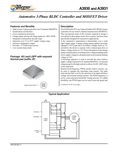
The A3930 and A3931 are 3‑phase brushless DC (BLDC) motor controllers designed for automotive use. They integrate most circuitry needed for a cost‑effective motor drive, support a wide supply range, and include a charge‑pump regulator that provides >10 V gate drive down to 5.5 V battery voltage. Features include high‑current 3‑phase gate drive, synchronous rectification, cross‑conduction protection, extensive diagnostics, and a low‑current sleep mode.
The datasheet provides detailed electrical and thermal characteristics, such as a 5.5 V to 50 V operating supply range, quiescent currents of 10 µA in sleep mode, and a V5 output of 4.75‑5.25 V. It also describes functional blocks like the high‑side/low‑side drivers, charge‑pump operation, Hall‑sensor inputs, and logic control pins, along with package information (48‑lead LQFP with exposed thermal pad).
| Supply voltage range | 5.5 V to 50 V |
|---|---|
| V5 output voltage | 4.75 V to 5.25 V |
| Gate‑drive voltage | >10 V |
| PWM frequency control | Set by external RC timing network |
| Hall sensor power | +5 V |
| Package | 48‑lead LQFP with exposed thermal pad |
The controller operates from 5.5 V up to 50 V supply voltage.
It provides a gate‑drive voltage greater than 10 V, even when the battery voltage is as low as 7 V.