
The UCC3808A family is a BiCMOS push-pull, high-speed, low-power, pulse-width modulator. The UCC3808A contains all of the control and drive circuitry required for off-line or dc-to-dc fixed frequency current-mode switching power supplies with minimal external parts count. The UCC3808A dual output drive stages are arranged in a push-pull configuration. Both outputs switch at half the oscillator frequency using a toggle flip-flop. The dead time between the two outputs is typically 60 ns to 200 ns depending on the values of the timing capacitor and resistors, thus limiting each output stage duty cycle to less than 50%.
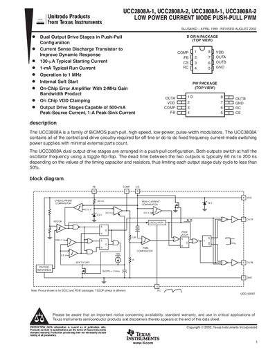
The UCC3808A and UCC2808A families are BiCMOS push‑pull, high‑speed, low‑power pulse‑width modulators used in off‑line or DC‑to‑DC fixed‑frequency current‑mode switching power supplies. Both devices integrate control and drive circuitry, providing dual output stages that operate in a push‑pull configuration with each output switching at half the oscillator frequency.
The datasheet details package options (SOIC, PDIP, TSSOP), electrical characteristics, pin assignments, and typical application circuits. It also includes ordering information, packaging data, and design notes such as oscillator programming, soft‑start implementation, and current‑sense functionality.
| Peak source current per output stage | 0.5 A |
|---|---|
| Peak sink current per output stage | 1 A |
| Oscillator frequency range | 175 kHz – 194 kHz |
| Supply voltage (VDD) | 10 V |
The dead time is typically 60 ns to 200 ns, depending on the timing resistor and capacitor values.
The supply current (IDD) is limited to ≤ 10 mA.