
ICL7106/7/7S is Intersil's high performance, low power, 31/2 digit A/D converter. It includes seven segment decoders, display drivers, a reference, and a clock. The ICL7106 is designed to interface with a liquid crystal display (LCD) and includes a multiplexed backplane drive; the ICL7107 will directly drive an instrument size light emitting diode (LED) display. ICL7106/7/7S brings together a combination of high accuracy, versatility, and true economy. It features auto- zero to less than 10µV, zero drift of less than 1µV/oC, input bias current of 10pA (Max), and rollover error of less than one count. True differential inputs and reference are useful in all systems, but give the designer an uncommon advantage when measuring load cells, strain gauges and other bridge type transducers. Finally, the true economy of single power supply operation (ICL7106), enables a high performance panel meter to be built with the addition of only 10 passive components and a display.
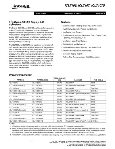
The ICL7106 and ICL7107 are low‑power 3‑½‑digit A/D converters with built‑in reference, clock and display drivers. The ICL7106 drives LCD displays with a multiplexed backplane, while the ICL7107 directly drives LED displays. Both devices feature auto‑zero accuracy better than 10 µV, zero drift under 1 nV/°C, and input bias currents of 10 pA max.
The datasheet lists absolute maximum ratings, electrical specifications, pin‑out diagrams for PDIP and MQFP packages, and typical application circuits. Package dimensions, thermal limits, and recommended external components are also provided, along with design notes on common‑mode handling and reference selection.
| Auto‑zero accuracy | < 10 µV |
|---|---|
| Zero drift | < 1 nV/°C |
| Input bias current | 10 pA max |
| Typical power dissipation | < 10 mW |
| Supply voltage (ICL7106) | single 9 V |
| Supply voltage (ICL7107) | dual +5 V |
| Maximum lead temperature for soldering (10 s) | 300 °C |
The ICL7106 typically dissipates less than 10 mW.
The typical input bias current is 1 pA, with a maximum of 10 pA.
Leads may be heated up to 300 °C for a 10‑second soldering process.