
The APR3001/2/3 from ANPEC Electronics Corp. are micro-power microprocessor reset circuits designed to monitor voltage supplies in μP and digital systems. With an extremely low quiescent current of typically 1.5 µA, they are ideal for portable battery operated equipment. The APR3001/2/3 operate by monitoring the system power supply voltage. When the input voltage drops below a fixed threshold, the device asserts a reset signal for a fixed time period after Vcc rises above the fixed threshold. The APR3001/2/3 series is available with three output stage versions: APR3001 push-pull active low output, APR3002 push-pull active high output, and APR3003 open drain active low output. They are also designed to reject fast line transient glitches on Vcc. The APR3001/2/3 are available in miniature SOT-23, SOT-23-5, and SOT-89 packages.
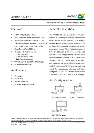
The APR3001/2/3 series are micro‑power reset circuits designed for computers, cell phones and other portable electronics. They feature a 1.2 V to 6 V input range, ultra‑low quiescent current (≤1.5 µA) and a fixed reset timeout of 250 ms. Three output versions are offered: push‑pull active low (APR3001), push‑pull active high (APR3002) and open‑drain active low (APR3003). The devices are supplied in SOT‑23, SOT‑23‑5 and SOT‑89 packages.
Typical applications include monitoring uP power supplies and generating a reset pulse when the supply drops below a programmed threshold. Electrical characteristics such as supply current, reset threshold, hysteresis and temperature performance are detailed in the datasheet, along with pin configurations, ordering information and reliability test data.
| Input Voltage Range | 1.2 V to 6 V |
|---|---|
| Reset Timeout Period | 250 ms |
| Output Configurations | Open‑drain, CMOS active high, CMOS active low |
| Package Types | SOT‑23, SOT‑23‑5, SOT‑89 |
| Maximum Continuous Input Current | 20 mA |
| Junction Temperature Range | -40 °C to 150 °C |
| Lead Temperature (soldering, 10 s) | 260 °C |
| Thermal Resistance (SOT‑23‑5) | 357 °C/W |
The devices operate with an input voltage from 1.2 V up to 6 V.
The reset output remains asserted for a fixed timeout period of 250 ms.
Three output configurations are offered: open‑drain, CMOS active high, and CMOS active low.
They are available in SOT‑23, SOT‑23‑5 and SOT‑89 surface‑mount packages.