
This manual introduces the E511 evaluation kit, including installation, usage, and troubleshooting
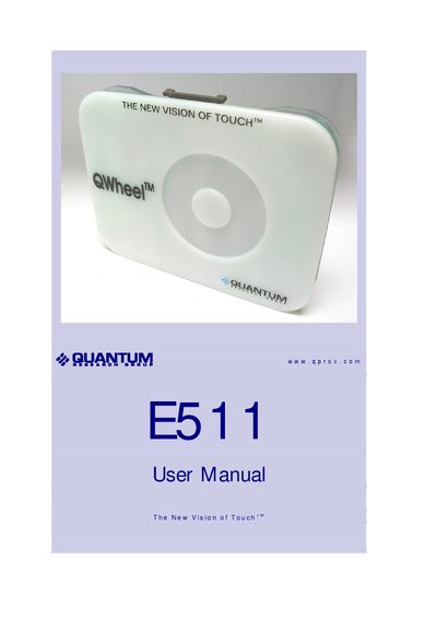
This manual describes the Quantum E511 evaluation kit, which includes the E511 board, a USB‑SPI adapter, cables, and QWheel software. It explains the kit contents, how to mount the spare board on a dielectric panel, and how to connect the assembly to a PC via the USB‑SPI adapter.
The guide also covers using the QWheel software to monitor touch signals, adjust parameters such as Threshold and Drift Compensation Rate, and perform calibration. A troubleshooting section lists common communication problems and their solutions.
| Output Ratio range | 0 to 127 |
|---|---|
| LED indicators | LED 1 = power, LED 2 = touch detection |
| LED 2 function | lights on each touch |
At the start of each session click the Calibrate button in the QWheel software while the assembly is positioned as it will be used.
Decrease the Threshold value in the QWheel software; the default is 25.