
The ZXLB1600 inductive switching boost converter accepts an input voltage of between 1.6V and 5.5V and provides an adjustable output voltage of up to 28V for LCD and OLED bias. The device contains an output switch and a second switch to isolate the coil from the input to provide true isolation in shutdown mode. The output can be adjusted by means of an externally applied dc voltage, a PWM control signal, or external feedback resistors and can supply typically 10mA of output current at maximum output voltage. Higher current is available at lower output voltages. The input voltage range accepts a number of battery solutions, including dual dry cell and single Li-Ion cells and PFM operation mode allows the output to be regulated with high efficiency under light or no load conditions. The switching frequency range permits the use of miniature surface mount inductors. A low battery comparator is provided to indicate when the input voltage has fallen to within ±2% of a preset threshold. This threshold is set internally, but can be adjusted externally to any voltage within the supply voltage range.
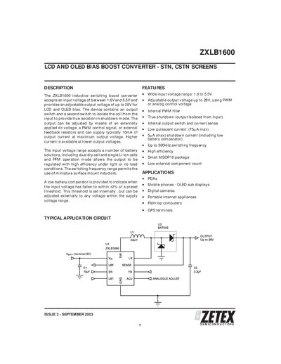
The ZXLB1600 is an inductive switching boost converter designed for LCD and OLED bias applications. It accepts a wide input voltage range of 1.6 V to 5.5 V and provides an adjustable output voltage up to 28 V, which can be set via an external DC voltage on the ADJ pin, a PWM control signal, or external feedback resistors. The device features low quiescent current, true shutdown isolation, and a high‑frequency switching capability up to 500 kHz.
Typical applications include PDAs, mobile phone sub‑displays, digital cameras, portable internet appliances, palmtop computers, and GPS terminals. The converter is offered in a small MSOP10 package and is supplied in reel form for easy assembly.
| Input voltage range | 1.6 V to 5.5 V |
|---|---|
| Adjustable output voltage | up to 28 V |
| Typical output current at max voltage | 10 mA |
| Quiescent current | 75 µA max |
| Shutdown current (max) | 5 A |
| Switching frequency | up to 500 kHz |
| Package | MSOP10 |
It operates with an input voltage from 1.6 V to 5.5 V.
The output voltage can be set by applying a DC voltage to the ADJ pin, using a PWM signal on the EN pin, or by external feedback resistors.
The device can handle up to 5 A of shutdown current.
It is supplied in a small MSOP10 surface‑mount package.