
This is a X200 series inverter quick reference guide, which introduces the power circuit and control circuit terminal connection information of the inverter, as well as the characteristics and features of the inverter
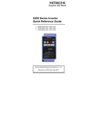
This Quick Reference Guide is intended for experienced users servicing existing Hitachi X200 Series inverter installations. It provides concise wiring diagrams, terminal assignments, keypad operation details, and safety warnings to help with troubleshooting and basic setup.
Key sections include power and motor wiring diagrams, control circuit terminal tables, keypad navigation, error code listings, analog input configuration, UL safety cautions, torque and wire‑size tables, and recommended circuit‑breaker and fuse sizes for both 200 V and 400 V models.
| Logic input voltage | +24 V DC |
|---|---|
| Analog voltage output range | 0 to 10 VDC, 1 mA max |
| Contact rating (resistive load) | 250 VAC, 2.5 A |
| Circuit‑breaker rating for 400 V class | 600 V rating |
Press the Stop/Reset key to reset the inverter and clear the error.
The Run/Stop LED is ON when the inverter output is ON and the motor is developing torque, and OFF when the output is OFF.
The relay contacts can handle up to 250 VAC at 2.5 A resistive load.