
Microchip's Enhanced FLASH Microcontroller devices have the capability of self-programming the program memory, providing the user with the ability to perform bootloading operations. This application note demonstrates a simple bootloader implementation for the PIC18F families of microcontrollers with a CAN module. It provides a low-level framework that can be used with higher-level network protocols to develop more complex and custom-tailored systems.
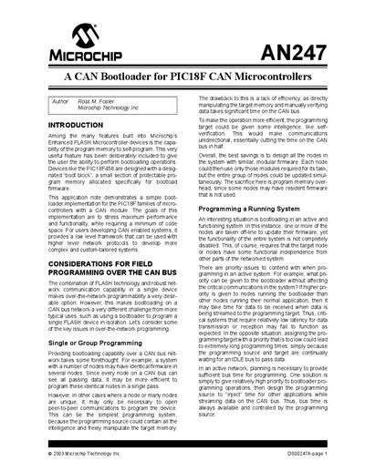
The AN247 note introduces a CAN bootloader that enables in‑field programming of PIC18F devices with a dedicated boot block. It describes how the bootloader can be triggered by hardware events (e.g., a button press after reset) or by a special CAN message, and discusses the trade‑offs of single‑node versus group programming over a CAN bus.
Key sections detail the memory organization (512‑byte boot block, program, EEPROM and configuration regions), the command set (PUT/GET, control bits, special commands), compile‑time options (PMode vs. PG Mode, self‑verification) and practical considerations such as write latency, vector remapping and debugging. The note provides example code snippets and guidance for both assembly and C implementations.
| Boot block size | 512 bytes |
|---|---|
| Program memory write latency | ≈2 ms per 8‑byte block |
| EEPROM write latency | ≈4 ms per byte |
| Maximum data per CAN frame | 8 bytes |
| Control register count | 8 registers (D0–D7) |
A single CAN frame can carry up to 8 bytes of programming data.
Boot mode can be entered by a hardware event such as pressing a button after reset, or by a network event like receiving a special CAN identifier.