
This data sheet introduces the core features, interrupt capability, hardware stack, timers, capture, compare, PWM module, etc. of PIC16C712 and PIC16C716 microcontrollers.
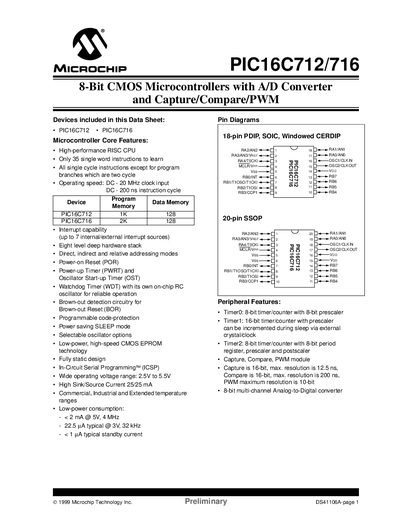
The PIC16C712 and PIC16C716 are 8‑bit CMOS microcontrollers with integrated A/D converters, capture/compare/PWM modules, and a range of I/O ports. The document details device architecture, memory organization, and peripheral features.
Key specifications include a 20 MHz maximum clock speed, 1 KB (PIC16C712) or 2 KB (PIC16C716) program memory, 128 bytes data memory, up to seven interrupt sources, and a supply voltage range of 2.5 V–5.5 V. Pin configurations are offered in 18‑pin PDIP, SOIC, windowed CERDIP, and 20‑pin SSOP packages.
| Maximum operating speed | 20 MHz |
|---|---|
| Program memory | 1 KB (PIC16C712) / 2 KB (PIC16C716) |
| Data memory | 128 bytes |
| Interrupt sources | up to 7 internal/external |
| Supply voltage range | 2.5 V to 5.5 V |
| Typical power consumption | <2 mA @ 5 V, 4 MHz |
The devices operate up to 20 MHz with a DC clock input.
They support up to seven internal or external interrupt sources.
The microcontrollers work from 2.5 V to 5.5 V.