
This document is the design manual of LM3590 evaluation board, which introduces the use method, circuit schematic and component information of the evaluation board.
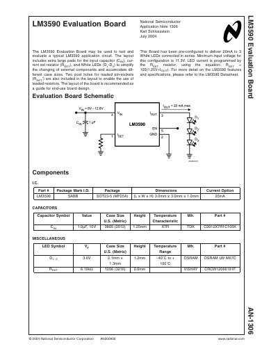
The LM3590 Evaluation Board is designed to test and evaluate typical LM3590 application circuits. It features extra‑large pads for the input capacitor, current‑set resistor, and three white LEDs, as well as post holes for leaded pin‑sockets to simplify component changes and accommodate different package sizes.
The board is pre‑configured to deliver 20 mA to three series‑connected white LEDs with a minimum input voltage of 11.3 V. LED current is set by the external RSET resistor, and the EN pin provides an active‑high enable/shutdown function. The manual includes schematic details, component listings, and compliance information.
| Maximum LED count and current | 3 white LEDs at 20 mA |
|---|---|
| Input voltage range | 6.0 V to 12.6 V |
| Maximum LED forward voltage | 11.5 V |
| Package type | 5‑pin SOT23 |
| EN pin internal pull‑down | 500 kΩ |
| Current‑set resistor equation | RSET = 100 × (1.25 V ÷ IOUT) |
| EN pin logic level | 1.5 V–1.8 V CMOS |
| Minimum input voltage for three LEDs | 11.3 V |
It can drive up to three white LEDs in series, each at a constant 20 mA.
The board operates from 6.0 V to 12.6 V, with a minimum of 11.3 V for the three‑LED configuration.
By connecting an external resistor (RSET) to the ISET pin using the formula RSET = 100 × (1.25 V ÷ IOUT).
The LM3590 is supplied in a small 5‑pin SOT23 package.