
The MAX5820 is a dual, 8-bit voltage-output, digital-to-analog converter (DAC) with an I2C-compatible, 2-wire interface that operates at clock rates up to 400kHz. It operates from a single 2.7V to 5.5V supply (115µA at VDD = 3.6V). The device features three software-selectable power-down output impedances: 100kΩ, 1kΩ, and high impedance. Other features include internal precision rail-to-rail output buffers and a power-on reset (POR) circuit that powers up the DAC in the 100kΩ power-down mode. The MAX5820 features a double-buffered I2C-compatible serial interface that allows multiple devices to share a single bus. All logic inputs are CMOS-logic compatible and buffered with Schmitt triggers, allowing direct interfacing to optocoupled and transformer-isolated interfaces. It minimizes digital noise feedthrough by disconnecting the clock (SCL) signal from the rest of the device when an address mismatch is detected. The MAX5820 is specified over the extended (-40°C to +85°C) temperature range and is available in a small 8-pin µMAX® package. Refer to the MAX5822 data sheet for the 12-bit version and to the MAX5821 data sheet for a 10-bit version.
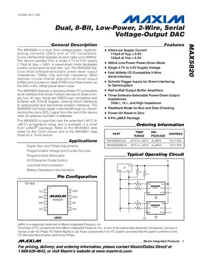
The MAX5820 is a dual 8‑bit voltage‑output DAC with an I²C/SMBus‑compatible 2‑wire interface, operating from a single 2.7 V to 5.5 V supply and supporting clock rates up to 400 kHz.
It offers ultra‑low supply current (115 pA typical), three selectable power‑down output impedances (100 kΩ, 1 kΩ, high‑impedance), rail‑to‑rail output buffers, and includes detailed pin descriptions, timing diagrams, and absolute‑maximum ratings.
| Supply Voltage Range | 2.7 V to 5.5 V |
|---|---|
| Resolution | 8 bits |
| Integral Nonlinearity (INL) | ≤ +1 LSB |
| Differential Nonlinearity (DNL) | ≤ +0.5 LSB |
| Gain Error | ≤ 0.8 % FSR |
| Serial Clock Frequency | up to 400 kHz |
| Ultra‑Low Supply Current (no load) | 115 pA (typical at Vpp = 3.6 V) |
| Power‑Down Output Impedances | 100 kΩ, 1 kΩ, High‑Impedance |
The MAX5820 supports a serial clock frequency up to 400 kHz.
The device provides 8‑bit resolution.
Three software‑selectable options: 100 kΩ, 1 kΩ, or high‑impedance.
It operates from 2.7 V to 5.5 V.