
This file is an installation manual that introduces the features and characteristics of the MRF/MWF1700 and DCPM1700 series rectifiers.
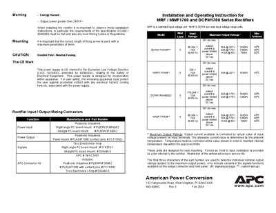
This manual provides the installation and operating instructions for APC MRF, MWF1700 and DCPM1700 series rectifiers. It outlines safety hazards, required compliance with IEC950/EN60950 and local wiring codes, and the CE marking requirements for the units.
The document details mounting procedures, recommended fixing screw length, input and output connector types, wiring diagrams, and signal connections. It also lists the electrical ratings such as input voltage range, output current, power, frequency, and ambient temperature limits.
| Input voltage range | 85‑264 V |
|---|---|
| Maximum output current | 30 A @ 207 V |
| Maximum output power | 1630 W |
| Operating frequency | 45‑65 Hz |
| Maximum ambient temperature (high‑power model) | 65 °C |
| Maximum ambient temperature (standard model) | 45 °C |
| Maximum fixing screw penetration | 6 mm |
Installation must meet the IEC950 / EN60950 specification and any local wiring codes or regulations.
The fixing screw should have a maximum penetration of 6 mm.
The rectifiers accept an input voltage from 85 V to 264 V.
A fan‑fail opto signal is provided on pin a2.