
This document describes the features and characteristics of the M41ST85Y and M41ST85W products. The products support 5.0V or 3.0V operating voltage and have a 512-bit (64 x 8) serial RTC and NVRAM supervisor. The products are optimized for minimal interconnect to MCU and have a 2.5 to 5.5V oscillator operating voltage. Additionally, the products have features such as automatic switch-over and deselect circuitry, choice of power-fail deselect voltages, programmable alarm and interrupt function, watchdog timer, microprocessor power-on reset, battery low flag, power-down timestamp, etc.
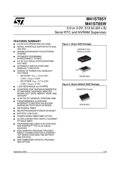
The M41ST85Y and M41ST85W are low‑power serial real‑time clock (RTC) and non‑volatile RAM (NVRAM) supervisors. They integrate a 32.768 kHz oscillator, 44 bytes of general‑purpose RAM, alarm, watchdog timer, square‑wave output and power‑fail detection, all accessible via a two‑wire I²C bus.
The devices are offered in a 28‑lead SOIC package with an optional SNAPHAT® top that combines the battery and crystal, or a 28‑lead SOIC with an embedded crystal (MX). They feature ultra‑low battery supply current (500 nA max) and a wide operating voltage range, making them suitable for battery‑backed timekeeping in microcontroller‑based systems.
| Operating voltage | 5.0 V or 3.0 V |
|---|---|
| Oscillator operating voltage | 2.5 V to 5.5 V |
| Battery supply current (low‑power mode) | 500 nA max |
| Memory size | 512 bit (64 × 8) |
| General‑purpose RAM | 44 bytes |
| Power‑fail deselect voltage (M41ST85Y) | Voc = 4.5‑5.5 V; Vprp = 4.20‑4.50 V |
| Power‑fail deselect voltage (M41ST85W) | Vcc = 2.7‑3.6 V; Vprp = 2.55‑2.70 V |
The M41ST85Y operates from 4.5 V to 5.5 V (Voc) with a power‑fail reference voltage between 4.20 V and 4.50 V.
The device draws a maximum of 500 nA in ultra‑low battery supply current mode.
It uses a two‑wire I²C (2‑wire) serial bus with SDA and SCL lines.
The device provides 44 bytes of general‑purpose RAM for user data.