
The MAX1966/MAX1967 are voltage-mode pulse-width-modulated (PWM), step-down DC-DC controllers that are ideal for a variety of cost-sensitive applications. They drive low-cost N-MOSFETs for both the high-side switch and synchronous rectifier and require no external Schottky power diode or current-sense resistor. Short-circuit and current-limit protection is provided by sensing the drain-to-source voltage on the low-side FET. Both devices can supply outputs as low as 0.8V and are well suited for DSP cores and other low-voltage logic. The MAX1966 has an input range of 2.7V to 5.5V while the MAX1967 has an input range of 2.7V to 28V. In ultra-low-cost designs, the MAX1966/MAX1967 can provide efficiency exceeding 90% and can achieve 95% efficiency with optimized component selection. The MAX1966/MAX1967 operate at 100kHz and accommodate aluminum electrolytic capacitors and powdered-iron core magnetics in minimum-cost designs. They also provide excellent performance with high-performance surface-mount components. The MAX1966 is available in a low-cost 8-pin SO package. The MAX1967 is available in a 10-pin µMAX package.
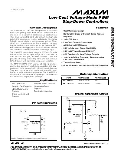
The MAX1966 and MAX1967 are voltage‑mode PWM step‑down DC‑DC controllers designed for cost‑sensitive applications. They drive low‑cost N‑MOSFETs for both the high‑side switch and synchronous rectifier, eliminating the need for external Schottky diodes or current‑sense resistors. Both devices can output voltages as low as 0.8 V and operate at a fixed 100 kHz switching frequency.
Key features include input voltage ranges of 2.7‑5.5 V (MAX1966) and 2.7‑28 V (MAX1967), thermal shutdown, output‑current‑limit and short‑circuit protection, and efficiencies exceeding 90 % (up to 95 % with optimized components). The MAX1966 is offered in an 8‑pin SO package, while the MAX1967 uses a 10‑pin µMAX package.
| Input voltage range (MAX1966) | 2.7 V to 5.5 V |
|---|---|
| Input voltage range (MAX1967) | 2.7 V to 28 V |
| Minimum output voltage | 0.8 V |
| Switching frequency | 100 kHz |
| Package (MAX1966) | 8‑pin SO |
| Package (MAX1967) | 10‑pin µMAX |
| Efficiency (typical) | >90 % (up to 95 % with optimized components) |
The MAX1966 operates with an input voltage from 2.7 V to 5.5 V.
The MAX1967 can accept an input voltage between 2.7 V and 28 V.
Both the MAX1966 and MAX1967 operate at a fixed 100 kHz switching frequency.