
The MAX1492/MAX1494 are low-power, 3.5- and 4.5-digit analog-to-digital converters (ADCs) with integrated liquid crystal display (LCD) drivers that operate from a single 2.7V to 5.25V power supply. They include an internal reference, a high-accuracy on-chip oscillator, and a triplexed LCD driver. An internal charge pump generates the negative supply needed for single-supply operation. The ADC can be configured for either a ±2V or ±200mV input range and outputs its conversion results to an LCD and/or to a microcontroller (µC). µC communication is facilitated through an SPI™-/QSPI™-/MICROWIRE™-compatible serial interface. The MAX1492 is a 3.5-digit (±1999 count) device, and the MAX1494 is a 4.5-digit (±19,999 count) device. The MAX1492/MAX1494 do not require external precision integrating capacitors, autozero capacitors, crystal oscillators, charge pumps, or other circuitry required with dual-slope ADCs commonly used in panel meter circuits. These devices also feature on-chip buffers for the differential signal and reference inputs, allowing direct interface with high-impedance signal sources. In addition, they use continuous internal-offset calibration and offer >100dB simultaneous rejection of 50Hz and 60Hz line noise. Other features include data hold and peak hold, overrange and underrange detection, and a low-battery monitor.
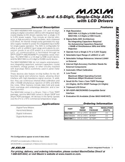
The MAX1492 and MAX1494 are low‑power analog‑to‑digital converters offering 3.5‑digit (±1999 count) and 4.5‑digit (±19,999 count) resolution respectively. They operate from a single 2.7 V to 5.25 V supply and include an integrated LCD driver, internal reference, charge pump and high‑accuracy on‑chip oscillator.
Key features include selectable ±2 V or ±200 mV input ranges, SPI/QSPI/MICROWIRE‑compatible serial interface, on‑chip differential buffers, continuous internal‑offset calibration, >100 dB line‑noise rejection, data‑hold/peak‑hold, over‑/under‑range detection, and a low‑battery monitor. Packages are 28‑pin SSOP/PDIP for MAX1492 and 32‑pin 7 mm×7 mm TQFP for MAX1494.
| Resolution (digits) | MAX1492: 3.5‑digit (±1999 count); MAX1494: 4.5‑digit (±19,999 count) |
|---|---|
| Supply voltage range | 2.7 V to 5.25 V |
| Selectable input range | ±2 V or ±200 mV |
| Maximum operating current | 960 µA (typical), 400 µA shutdown |
| Package types | MAX1492: 28‑pin SSOP, 28‑pin PDIP; MAX1494: 32‑pin 7 mm×7 mm TQFP |
| Low‑battery monitor threshold | 2.048 V |
| Line‑noise rejection | >100 dB simultaneous 50 Hz/60 Hz rejection |
They operate from a single 2.7 V to 5.25 V power supply.
MAX1492 provides 3.5‑digit (±1999 count) resolution, while MAX1494 provides 4.5‑digit (±19,999 count) resolution.
The devices support SPI‑, QSPI‑ or MICROWIRE‑compatible serial interfaces.
The low‑battery monitor trips at 2.048 V.