
MAX5977A evaluation board is a hot swap controller board to control the turn on of large power and large capacitance loads to avoid spikes in the power supply. The evaluation circuit uses MAX5977A fault-locked, 20-pin TQFN surface-mount package (with bare solder pads) hot swap controller IC. The evaluation board operates in the 1V to 16V input power range, and the power is connected to the VIN and GND connectors. The IC controls two n-channel MOSFETs, and provides up to 40A of output current. The evaluation board circuit ensures that the output voltage is stable and within the undervoltage (UV) and overvoltage (OV) threshold range. The circuit continuously monitors the load current to ensure that it does not exceed the programmable fast and slow current limiting thresholds. The evaluation board provides a buffered output for the IC's current sensing amplifier, including a precision current source. When the IC calibration mode function is enabled, a 2.5V output is provided. By replacing U1, the evaluation board can also be used to evaluate the MAX5977B auto-retry hot swap controller.
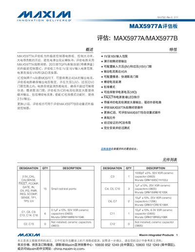
The MAX5977A/MAX5977B evaluation kit is a high‑current controller board that operates from 1 V to 16 V and can deliver up to 40 A (peak 50 A) through external n‑channel MOSFETs. The board includes a full component list, power‑supply connections, LED status indicators and configurable jumpers for quick setup.
The manual describes the calibration mode, which is selected with SW1 and uses a precision 2.5 × 10³ S gain amplifier. LED D5 shows normal operation while LED D4 signals a current‑limit fault. Detailed pin‑out tables, safety precautions and wiring diagrams guide the user through installation and testing.
| Input voltage range | 1 V – 16 V |
|---|---|
| Maximum output current (continuous) | 40 A |
| Maximum output current (peak) | 50 A |
| Output voltage options | 12 V, 3.3 V, 2.5 V |
| MOSFET rating | 25 V, 100 A n‑channel |
| Calibration amplifier gain | 2.5 × 10³ S |
The board operates from 1 V up to 16 V.
LED D5 indicates normal operation, while LED D4 signals a current‑limit fault condition.