
This document is the datasheet of C8051F132, which introduces the characteristics and features of the product
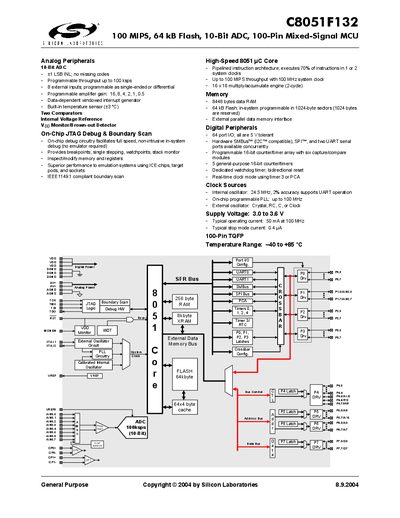
This handbook describes the C8051F132 mixed‑signal microcontroller, highlighting its 100 MIPS 8051 core, 64 kB Flash, 10‑bit ADC, and extensive analog and digital peripherals. It includes information on the on‑chip debug, JTAG, boundary‑scan, and clocking options.
The document also lists the electrical specifications, package dimensions, and pin‑out details, making it a reference for designers integrating the device into their systems.
| Supply Voltage | 3.0–3.6 V |
|---|---|
| CPU Active Supply Current (100 MHz) | 50 mA |
| Supply Current (1 MHz) | 0.6 mA |
| Oscillator Frequency | 24.5 MHz typical |
| PLL Frequency | up to 100 MHz |
| ADC Resolution | 10 bits |
| ADC Integral Nonlinearity | +1 LSB |
| ADC Throughput Rate | 100 ksps |
| Digital I/O Ports | 64 ports (5 V tolerant) |
| Maximum CPU Throughput | 100 MIPS at 100 MHz |
The device operates from 3.0 V to 3.6 V.
It features a 10‑bit analog‑to‑digital converter.
The microcontroller has 64 port I/O pins, all 5 V tolerant.
The core can achieve up to 100 MIPS when running at 100 MHz.