
This datasheet provides detailed information on the C8051F131 100 MIPS, 128 kB Flash, 10-Bit ADC, 64-Pin Mixed-Signal MCU.
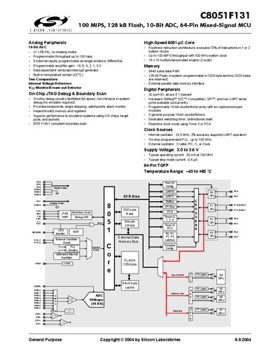
The C8051F131 is a 64‑pin mixed‑signal microcontroller featuring a 100 MHz 8051 core, 128 kB Flash, 10‑bit ADC, and a range of digital peripherals including UART, SPI, SMBus, and programmable timers. It operates from 3.0 V to 3.6 V and includes on‑chip JTAG debug and boundary‑scan capabilities.
Key analog blocks include a 10‑bit ADC with up to 100 ksps throughput, two comparators, an internal voltage reference, and a temperature sensor. Digital resources comprise 32 I/O pins, three UARTs, SPI, SMBus, and a 16‑bit counter/timer array. The device supports both internal and external clock sources, with a programmable PLL up to 100 MHz.
| Supply Voltage | 3.0 V – 3.6 V |
|---|---|
| Operating Current (100 MHz) | 50 mA |
| Flash Memory | 128 kB |
| Data RAM | 8448 bytes |
| ADC Resolution | 10 bits |
The ADC provides a 10‑bit resolution.
It operates from 3.0 V to 3.6 V.
The internal PLL can generate up to 100 MHz.
The MCU provides 32 port I/O pins, all 5 V tolerant.