
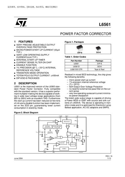
The L6561 is a power factor corrector IC offering very precise adjustable output, micro‑power start‑up current and a totem‑pole output capable of driving MOSFETs or IGBTs up to ±400 mA. It operates over a wide input voltage range (85 V – 265 V) and includes built‑in over‑voltage protection, a zero‑current detector and a disable function.
The datasheet provides absolute maximum ratings, thermal data, pin descriptions, detailed electrical specifications, and example application circuits for AC‑DC adapters, electronic lamp ballasts and SMPS designs. Evaluation results and revision history are also included.
| Start‑up Current (typ) | 50 µA |
|---|---|
| Quiescent Current (typ) | 4 mA |
| Totem‑pole Output Current | ±400 mA |
| Supply Voltage Range | 85 V – 265 V |
| Operating Temperature Range | -40 °C – 150 °C |
The L6561 has a typical start‑up current of 50 µA.
The totem‑pole output stage can source and sink up to ±400 mA.
Connecting the ZCD pin to ground disables the device, reducing supply current to about 1.4 mA typical.
The device operates from 85 V to 265 V input voltage.