
isl6414 is an ultra-low noise triple output LDO regulator with microprocessor reset circuit and is optimized for powering wireless chipsets. The IC accepts an input voltage range of 3.0V to 3.6V and provides three regulated output voltages: 1.8V (LDO1), 2.84V (LDO2), and another ultra clean 2.84V (LDO3). On-chip logic provides sequencing between LDO1 and LDO2 for BBP/MAC and I/O supply voltage outputs. LDO3 features ultra low noise that does not typically exceed 30µV RMS to aid VCO stability. High integration and the thin Quad Flat No-lead (QFN) package makes ISL6414 an ideal choice to power many of today’s small form factor industry standard wireless cards, such as PCMCIA, mini-PCI and Cardbus-32. The ISL6414 uses an internal PMOS transistor as the pass device. The SHDN pin controls LDO1 and LDO2 outputs whereas SHDN3 controls LDO3 output. Internal voltage sequencing insures that LDO1 output (1.8V supply) is always stabilized before LDO2 is turned on. When powering down, power to the LDO2 is removed before the LDO1 output goes off. The ISL6414 also integrates RESET function, which eliminates the need for additional RESET IC required in WLAN applications. The IC asserts a RESET signal whenever the VIN supply voltage drops below a preset threshold, keeping it asserted for at least 25ms after VIN has risen above the reset threshold. An output fault detection circuit indicates loss of output voltage.
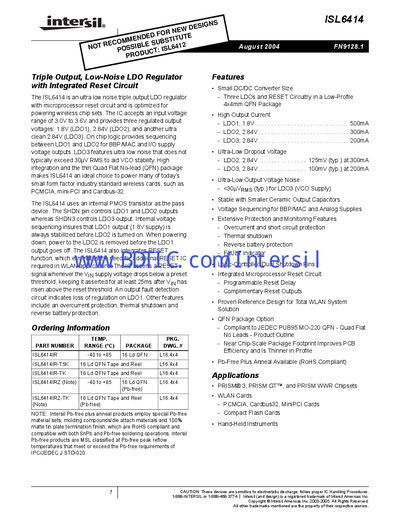
The ISL6414 is an ultra‑low‑noise triple‑output LDO regulator with an integrated microprocessor reset circuit, optimized for powering wireless chipsets. It accepts a 3.0 V to 3.6 V input and delivers three regulated outputs: 1.8 V, 2.84 V, and a second 2.84 V low‑noise supply.
The document includes ordering information, pinout diagrams, functional block diagrams, absolute maximum ratings, detailed electrical specifications, typical performance curves, and package dimensions. It also outlines protection features such as over‑current, thermal shutdown, and reverse‑battery protection.
| LDO1 output voltage | 1.8 V |
|---|---|
| LDO2 output voltage | 2.84 V |
| LDO3 output voltage | 2.84 V |
| LDO3 output voltage noise | <30 µV RMS |
| Protection features | Over‑current, thermal shutdown, reverse‑battery protection |
It provides three outputs: 1.8 V (LDO1), 2.84 V (LDO2), and 2.84 V (LDO3).
Yes, it has an integrated microprocessor reset circuit with programmable delay.