
This document describes the features and characteristics of the ADF9010 Rev. 0 analog RF front end for the 900 MHz ISM band.
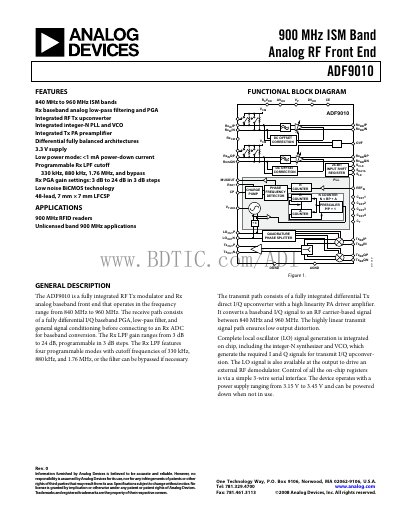
The ADF9010 is a fully integrated RF Tx modulator and Rx analog baseband front end that operates in the 840 MHz to 960 MHz ISM band. It includes a differential I/Q baseband PGA, programmable low‑pass filter, and an integer‑N PLL with on‑chip VCO for transmit up‑conversion.
The handbook contains functional block diagrams, detailed specifications for transmit and receive paths, pin configuration, absolute maximum ratings, write timing characteristics, and design guidelines such as PCB recommendations and ordering information.
| Operating Frequency Range | 840 MHz – 960 MHz |
|---|---|
| Supply Voltage (AVop/DVpp) | 3.15 V – 3.45 V |
| Transmit Output Power (typical) | 3 dBm |
| Transmit P1 dB Output Power | 10 dBm |
| Rx PGA Gain Range | 3 dB – 24 dB (3 dB steps) |
| Rx LPF Cutoff Frequency (Mode 0) | 320 kHz |
| Rx LPF Cutoff Frequency (Mode 1) | 880 kHz |
| Rx LPF Cutoff Frequency (Mode 2) | 1.76 MHz |
| Rx LPF Cutoff Frequency (Mode 3) | 4 MHz |
The device operates from 840 MHz to 960 MHz.
It requires an analog and digital supply between 3.15 V and 3.45 V.
The Rx PGA gain can be programmed from 3 dB to 24 dB in 3 dB steps.
Typical output power is 3 dBm, with a P1 dB point of 10 dBm.