
The ADP1828 is a synchronous buck PWM step-down DC-to-DC controller with a wide range of bias voltage, power stage input, and output voltage. It features an all N-channel MOSFET design, fixed-frequency operation, clock output, internal linear regulator, voltage tracking, and soft start.
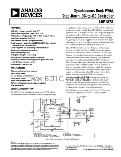
The ADP1828 is a synchronous buck PWM controller that supports a wide input voltage range and provides an adjustable output from 0.6 V up to 85 % of the input voltage. It integrates an internal linear regulator, soft‑start, thermal overload protection, and a power‑good indicator, making it suitable for telecom, networking, consumer electronics, and industrial power‑supply applications.
The document includes a feature summary, application examples, electrical specifications, absolute maximum ratings, pin‑out descriptions, block diagrams, typical application circuits, and layout guidelines. It also provides ordering information and compliance notes for the 20‑lead QSOP package.
| Input Voltage (internal regulator mode) | 5.5 V – 18 V |
|---|---|
| Input Voltage (direct mode) | 3.0 V – 5.5 V |
| Quiescent Current (typical) | 3.0 mA |
| Shutdown Current (minimum) | 5 µA |
| Operating Junction Temperature | -40 °C to +125 °C |
| Switching Frequency | 300 kHz or 600 kHz fixed; 300 kHz – 600 kHz adjustable |
| Output Voltage Range | 0.6 V to 85 % of input voltage |
| Shutdown Supply Current | 15 pA |
The FREQ pin selects a fixed 300 kHz (low) or 600 kHz (high) frequency, and a resistor from FREQ to GND allows a free‑running frequency between 300 kHz and 600 kHz.
Yes, it contains an internal LDO that provides a 5 V output for biasing when VIN exceeds 5.5 V.
The device provides soft‑start, thermal overload shutdown, undervoltage lockout, over‑voltage detection, and a power‑good indicator.