
The ADG428/ADG429 are analog multiplexers with low on resistance, low power consumption, and high speed.
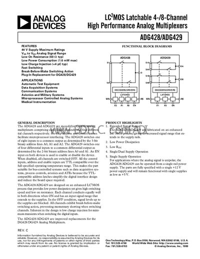
The ADG428 is an 8‑channel latchable analog multiplexer, while the ADG429 provides 4 differential channels. Both devices feature TTL‑compatible address and enable inputs, low on‑resistance (≈60 mΩ typ), low power consumption (≈1.6 mW max), and break‑before‑make switching to prevent shorting. They are designed for bus‑controlled systems such as data acquisition, test equipment, avionics, and medical instrumentation.
The parts support dual‑supply operation (±15 V) and single‑supply operation down to +5 V, with extended signal range to the supply rails. They include ESD protection, low charge injection (<4 pC typ), and are offered in multiple packages (DIP, PLCC, SOIC, Cerdip) for various temperature ranges.
| Supply Voltage Range (Dual Supply) | ±15 V |
|---|---|
| On‑Resistance (Ron) typical | 60 mΩ typ |
| Power Consumption (max) | 1.6 mW |
| Charge Injection | < 4 pC typ |
| Switching Transition Time | 110 ns typ |
| OFF Leakage Current (Source) | 0.03 nA typ |
| Operating Temperature Range (B Version) | -40 °C to +85 °C |
| Package Options | DIP, PLCC, SOIC, Cerdip |
The devices are rated for a dual‑supply range of ±15 V.
The typical on‑resistance is about 60 mΩ.
They are offered in DIP (N‑18), PLCC (P‑20A), SOIC (R‑18), and Cerdip (Q‑18) packages.
Charge injection is specified as less than 4 pC typical.