
The AD2S90 is a complete 12-bit resolution tracking resolver-to-digital converter. No external components are required to operate the device. The converter accepts 2 V rms ± 10% input signals in the range 3 kHz–20 kHz on the SIN, COS and REF inputs. A Type II servo loop is employed to track the inputs and convert the input SIN and COS information into a digital representation of the input angle. This document describes the features and characteristics of the AD2S90, as well as its applications in industrial motor control, servo motor control, industrial gauging, encoder emulation, automotive motion sensing and control, factory automation, and limit switching.
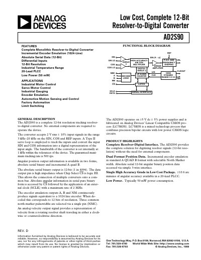
The AD2S90 provides a complete monolithic solution for converting resolver signals to digital data. It offers 12‑bit resolution, incremental encoder emulation (1024‑line), absolute serial output, and operates from a ±5 V supply with typical power consumption of 50 mW. The device includes differential inputs, a Type II servo loop, and a serial interface for easy integration.
The datasheet details electrical specifications, pin descriptions, timing characteristics, and recommended operating conditions. It also includes application notes on interfacing the converter to DSPs and microprocessors, as well as guidelines for wiring and ESD protection.
| Resolution | 12‑bit |
|---|---|
| Supply Voltage | ±5 V (±5 % tolerance) |
| Power Consumption | Typical 50 mW |
| Bandwidth | 1 kHz (typical) |
| Maximum Tracking Rate | 500 rps |
| Angular Accuracy | ‑10.6 arc min to +1 LSB |
| Input Voltage Amplitude | 2 V rms ± 10 % |
| Input Frequency Range | 3 kHz – 20 kHz |
| Incremental Encoder Emulation | 1024 lines (12‑bit equivalent) |
| Package | 20‑lead PLCC |
The device operates from a +5 V and –5 V supply, each with a ±5 % tolerance.
The AD2S90 outputs a 12‑bit absolute serial angular position (1 in 4096).
The maximum tracking rate is 500 revolutions per second.
Each input accepts a 2 V rms signal with ±10 % tolerance over 3 kHz to 20 kHz.