
The AD7722 is a complete low power, 16-bit, Σ-∆ ADC from Analog Devices. It operates from a 5 V supply and accepts a differential input voltage range of 0 V to +2.5 V or ±1.25 V centered around a common-mode bias. The AD7722 provides 16-bit performance for input bandwidths up to 90.625 kHz.
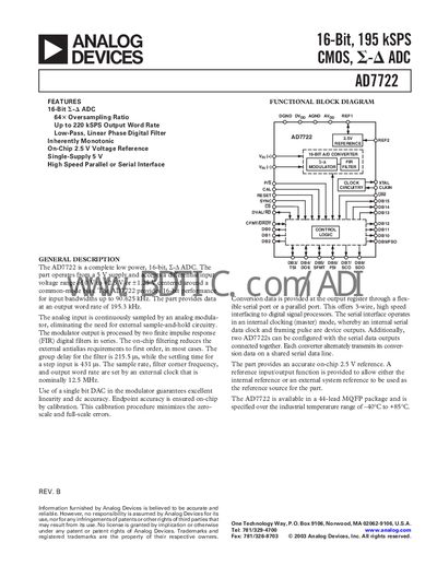
The AD7722 is a low‑power, 16‑bit, 195 kSPS CMOS ADC that integrates a 2.5 V on‑chip reference and operates from a single 5 V supply. It features a continuous‑sampling modulator, FIR digital filters, and offers both high‑speed parallel and serial interfaces for data output.
The device is supplied in a 44‑lead MQFP package, rated for industrial temperatures from –40 °C to +85 °C, and includes comprehensive pin functions, timing specifications, and absolute‑maximum ratings for reliable integration into signal‑processing systems.
| Resolution | 16 Bits |
|---|---|
| Maximum Output Word Rate | 195 kSPS |
| Input Bandwidth | 0 kHz – 90.625 kHz |
| Power Consumption | 375 mW |
| Operating Temperature Range | -40 °C to +85 °C |
| On‑Chip Reference Voltage | 2.5 V |
| Package | 44‑lead MQFP |
The AD7722 can output data at up to 195 kSPS word rate.
It operates from a single 5 V supply (AVpp and DVpp 5 V ± 5%).
The device provides a high‑speed parallel or serial interface for data output.
A logic‑high pulse on the CAL pin for one CLKIN cycle initiates a gain and offset calibration sequence.