
AD9200 is a monolithic, single supply, 10-bit, 20 MSPS analog-to-digital converter with an on-chip sample-and-hold amplifier and voltage reference.
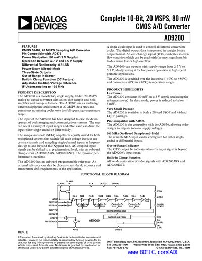
The AD9200 is a monolithic, single‑supply, 10‑bit, 20 MSPS analog‑to‑digital converter with an on‑chip sample‑and‑hold amplifier and programmable reference. It offers low power consumption, selectable input ranges, and both single‑ended and differential operation, making it suitable for imaging and communications systems.
The document provides full electrical specifications, pin‑out tables, functional block diagrams, layout recommendations, and mechanical dimensions for the 28‑lead SSOP and 48‑lead LQFP packages. It also describes operating modes, three‑state outputs, and out‑of‑range indication to aid designers in integrating the device into high‑speed mixed‑signal designs.
| Resolution | 10 Bits |
|---|---|
| Conversion Rate | 20 MHz |
| Power Consumption (typical) | 80 mW |
| Supply Voltage (AVDD/DRVDD) | 2.7 V – 5.5 V |
| Differential Nonlinearity (DNL) | +0.5 LSB |
| Integral Nonlinearity (INL) | +0.75 LSB |
| Input Bandwidth (0 dB) | 300 MHz |
| Package Types | 28‑lead SSOP and 48‑lead LQFP |
| Out‑of‑Range Indicator | OTR bit |
The AD9200 consumes about 80 mW at a 3 V supply, and drops to below 1 mW in sleep mode.
The device is offered in a 28‑lead SSOP package and a 48‑lead LQFP package.
The input voltage span can be set from 0.5 V to 2.5 V, selectable via reference pins.
An OTR output bit is asserted when the input signal exceeds the device’s input range.